THE MORRIS CANAL AND ITS
INCLINED PLANES.
Scientific American Supplement—February 24, 1883
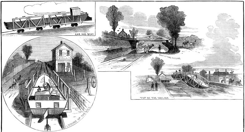
The illustrations contained within are of the Inclined Plane
at Bloomfield, N. J.
By HERBERT M. WILSON, C.E. ('81).
THE difficulty of raising canal boats over great falls, requiring
a series or flight of locks, considerable time, and great expenditure
of water in the operation, led to the adoption of other means,
viz.: (1) perpendicular shafts; (2) inclined lifts, or planes.
The former, though used on the Great Western Canal, England, are
not of a sufficiently extended application to require attention.
The inclined lifts, however, have been, and are at all times,
for falls of considerable height, the most economical. Like many
other things, these lifts were first carried out by the Chinese.
The first application, however, to modern canal systems is due
to William Reynolds who introduced them, in 1792, in the Shropshire
Canal. Subsequently, this system came into extended use on the
canals of England.
THE MORRIS CANAL.
This canal was chartered December 31, 1824; began July, 1825,
and completed from the Delaware River to Newark, during August,
1831, and extended to Jersey City in 1836. The planes and locks
were enlarged in 1841. Its original dimensions were as follows:
Canal—width at bottom, 20 feet; at top, 32 feet; depth of
water, 4 feet. Locks—chambers, 9 feet wide by 75 feet long
between miter-sills. Planes—to correspond with locks, first
constructed on various plans, 20 summit and 3 lock-planes in all.
The boats carried cargoes of 20 gross tons. During the winter
of 1835-36, the summit-planes were altered to lock-planes. They
were widened 2 feet, and the lock chambers enlarged to 11 by 95
feet in 1841. The canal was sold in 1844, and the new company
organized October 21, 1844. In 1845, the canal was enlarged, the
width being 25 feet at the bottom, and 40 feet at the top, and
the depth increased to 5 feet. The section boats were first introduced
in 1845, and carried cargoes of 45 gross tons. From 1850 to 1860,
all the planes were again altered to summit-planes, rebuilt, and
adapted to wire-rope haulage.
Elevations:
Mean tide-water to canal summit.
12 inclined planes 757 feet.
16 lift locks 157 feet.
Rise and Fall 914 feet.
Delaware River (low water) to canal summit.
11 Inclined planes 691 feet.
7 Lift locks 69 feet.
Rise and Fall 760 feet.
Total rise and fall 1,674 feet
Summary of Cost in Round Numbers.
From Delaware River to Newark $2,000,000
Alterations of planes in 1835-36 $230,000
Extension to Jersey City in 1836 $600,000
Greenwood reservoir and feeder $170,000
Enlarging planes and locks in 1841 $400,000
Total $3,400,000
Enlarging canals and rebuilding planes $1,700,000
Total cost $5,100,000
The greatest rise in any plane is 100 feet, its length being
1,600 feet (near Washington, N. J.). The summit is at Port Morris,
41.34 miles from the Delaware River, and 60.80 miles from the
Hudson River. The least rise of any plane is 44 feet. It is 3.4
miles from the Delaware, and 99.11 miles from the Hudson River.
The whole length of the canal is 102.15 miles, the longest level
(at Paterson) being 17.5 miles.
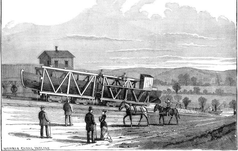
The boats, which are in two sections, are joined together by
latches and steadying-pins, the ends abutting against, each other.
Transverse partitions of wood separate the two compartments, each
of which is really a boat by itself. The average tonnage is about
65 tons, but the planes can transfer boats of as much as 100 tons
weight. The sectional system of boats was not adopted to suit
the planes, but was previously introduced. It is, however, of
great advantage in the use of the planes.
The first of the class of planes at present in use was introduced
in 1848, at a cost, including machinery, of $27,835. It is 900
feet long, and the fall 51 feet. It superseded six locks.
The track of the plane in each case runs a short distance along
the bottom of the lower bay, underwater, rises up the incline
to above the water level of the upper reach, then descends into
the upper reach and rung a few feet along the bottom. The grade
of the inclines is, in general, about 1 to 11.
The trucks which carry the boats, are, like the boats, divided
into two sections, each section having eight wheels with flanges
on each side of the rails. They are provided with strong stanchions,
to which the boats are fastened with hawsers.
The planes are in each case worked by a reaction waterwheel,
and the levers for regulating the supply of water and for the
control of the brakes are in a high tower, from which the man
in charge can see the whole plane. This tower contains also the
water-wheels and other machinery, and is about midway between
top and bottom of the plane and at the end of the flume.
The water-wheels have four arms and describe a circle 12 feet
in diameter. The openings for efflux of water at the ends of the
arms are 15½ inches high by 3½ inches wide, and
the wheel is placed far enough down the incline to get a head
of 45 feet. The discharge is 1,000 cubic feet per minute, and
235 horse-power produced.
The quantity of water needed for these wheels is less than
one-twentieth of the amount expended in a aeries of locks of the
same total height or lift.
The first boat tried on the plane, which was opened in 1848,
was taken up in 3½ minutes, the weight of boat. and cargo
being 70 tons.
These inclines were constructed under the direction of Messrs.
Ass Whitney and W. H. Talcot, chairman and engineer of the company.
The wire rope and the trucks used on these planes were manufactured
by J. A. Roebling & Sons, of Trenton. The winding drum is
12 feet in diameter, and is worked by the water wheel; it has
a continuous spiral groove of 3 inch pitch in its periphery. The
rope is fastened at opposite sides of the drum, so that, as one
end winds, the other unwinds. The motion is rendered reversible
by a clutch on the jack-shaft of the water-wheel.
The Stanhope plane is of the same general type as all the planes
west of the summit, and may be taken as an example.
The plane has a single track of two lines of heavy steel rails,
12 feet 4½ inches from center to center. The rails are
3-and-one-eighth inches broad at top, 3½ inches high, and
weigh 76 pounds to the yard. They are spiked to longitudinal stringers
of wood 6 inches high by 8 inches wide, resting at intervals on
large flat stones two-thirds embedded in the ground.
The car or cradle is in two sections, fastened together by
a chain and a link. Each section is provided with snubbing posts,
by which the boat is secured in the proper position as it floats
into the car. Long "fender" boards on each side serve
to support the boat when it is hauled from the water.
The wire cables are so arranged, that as one winds on the drum
the other unwinds. The two ropes pass around submerged horizontal
sheaves at the bottom and top of the plane. The car has a wire
rope attached at both ends, the "back rope" to one section,
and the main rope to the other. The latter is fastened to a small
drum on the car, by which the slack can be taken up and the rope
kept taut. Each section of the car has eight double-flanged wheels,
provided with brakes.
If the car is to be drawn out of the lower reach and up the
plane into the upper bay, all that is necessary is for the engineer
in the plane-house, called the "plane-man," to turn
the "tub-wheel" which lets the water into the reaction
water-wheel, and the drum winds up the cable at one end and unwinds
it at the other, drawing the car up.
To take a boat down the plane, if it is empty, it is hauled
out of the upper reach, the water shut off the wheel, and the
car allowed to descend by its own weight. A boy on the car can
apply the brake if the speed of descent becomes too great. If
the boat is loaded, the plane-man puts on about half water—that
is, opens the tub sufficiently to allow one-half the amount of
water for full power of wheel. This prevents the boat from going
down too fast. The planes west of the summit are uniform; those
east of it vary somewhat. At Drakesville, for instance, the plane
is 1,770 feet long from center of wheel pit to center of wheel
pit; its total rise is 50 feet—grade 1 in 10; it requires
3,900 feet of cable to work it, and the total head on the wheel
is 30 feet. It differs mainly from the Stanhope plane in having
but two lines of cable instead of four, and but two grooved pulleys.
This simplifies the construction materially, and makes a great
saving in wire cable, pulleys, pulley-block stands, etc. Besides,
the plane woks more easily, and there is less slack. Instead of
passing out in the same direction from opposite ends of the perpendicular
diameter of the drum, it passes out in opposite directions from
the same end of the diameter. Instead of being carried all the
way on small pulleys, the cable is supported near the water's
edge on two large vertical 11 or 14 foot groove-wheels. These
wheels are in large masonry pits or slots in the ground, so that
their upper surface is but a little above the surface of the ground.
All of the east side plane-houses are two stories high above
the ground, instead of three stories, as on the west side, the
brake and reversing-lever attachments being thereby greatly simplified.
All of the water-wheels are covered with a plate of iron, above
and below; this entirely covers them, excepting a few inches over
the nozzle. In all other respects these planes are entirely similar
to the one at Stanhope.
At Washington and at Newark, there are planes of a different
construction. These are double-tracked, two double lines of rails
running parallel and the whole length of the plane. There are
two cars, one ascending while the other descends, meeting half
way. The cable is arranged as at Stanhope. This arrangement relieves
the machinery of part of its work, as the descending car helps
in raising the other one.
From careful observation, I find that to take a loaded boat
up the plane at Stanhope, from the time it starts below until
it just floats in the upper bay, it takes from 5 minutes 10 seconds
to 6 minutes, the average being about 5 minutes 30 seconds. For
lowering a loaded boat, on the average, about 2 minutes 40 seconds
are required; for an empty boat, 2 minutes 50 seconds. For an
empty car, without boat, 2 minutes 45 seconds. As it would take
about four such planes in length to make a mile, it would require
11 minutes to draw an empty boat a mile up such a plane. For a
descending loaded boat, 9 minutes; for an ascending loaded boat,
22 minutes. These figures are as near as can be approximately
reckoned, and equal the ordinary rate of travel of the boats when
drawn by mules, about one mile in 30 minutes loaded, and one mile
in 20 minutes unloaded. Hence we see that, unlike the locks, the
boats are being raised and at the same time proceed at their ordinary
rate of travel; for, although while on the plane the speed is
somewhat greater than in the canal, allowance must be made for
the few minutes spent in getting the boats into the car; besides,
in going a mile, the boat rises vertically about 300 feet on this
particular plane.
From the above we find that while a boat takes probably about
8 minutes to go through a lock of 6 feet rise, to go through a
flight of 12 locks, equal to a plane with a rise of 70 feet, would
take 96 minutes; and during all this time a boat not only, in
passing a plane, loses nothing in horizontal motion, but by the
saving of time is enabled to advance about five miles while the
other boat is passing the locks. The saving of time is evidently
considerable.
On the whole canal there are twenty-three planes, with an average
lift and length of that at Stanhope—the total length six
miles. It takes the empty boats 66 minutes and loaded boats 198
minutes to travel this distance, and as there are as many boats
going down as there are going up, the average time consumed
in traveling these six miles is 133 minutes or one mile in 22
minutes, which is better than ordinary canal speed.
If, instead of these planes, there were twenty-three flights
of locks, each one consuming 96 minutes in its passage, the whole
would require a loss of 36 hours, or in distance—at the rate
of one mile in 22 minutes—of 100 miles!
The cargoes carried on this canal are almost exclusively coal
and ore, with occasionally a load of grain or wood. Of wood, grain,
or coal, the boats take a full load to sink to the water-line,
but ore being heavier for the same bulk, a very little in the
bottom is all they can carry. The usual load is 70 tons, but sometimes
75 and 80 tons are carried; the latter, however, is uncommon.
The empty boats weigh from 14 to 18 tons, average 17 tons. The
cars alone weigh from 38 to 45 tons, and average 40 tons; hence,
the average weight raised on the planes is 127 tons, and it may
be as high as 143 tons.
The grades are never very steep; at Stanhope the grade is about
1 in 10; at Port Morris it is 1 in 20; the steepest, 1 in 9; average
grade, 1 in 11.
Expenses.—The first cost of a plane considerably
exceeds that of a single lock, as do also the running expense,
repairs, etc. A plane with a rise of 70 feet, however, will cost
very nearly the same as a flight of six locks of a rise of 12
feet each.
The wire cable costs about $l per foot, and needs replacing
about once in three years. The large drum costs about $3,000,
and lasts many years. The entire machinery needs replacing about
once in ten years, with the exception of the drum and shafts,
which last much longer. In locks there is very little repairing
to be done, with the exception of the wickets, which do not last,
but are small and cheap.
We will compare an average plane, as that at Stanhope, with
a lift of 72 feet, with a flight of twelve locks lifting each
6 feet. For a loaded boat, the plane takes 5 minutes 30 seconds
= 330 seconds for passage. The water in the flume lowers 7 inches
and flows at a velocity of 120 feet in 60 seconds = 2 feet in
1 second. The flume is 8 feet wide; hence the wheel consumes 8'
x 2' = 16 square feet of water per second; this multiplied by
7" in depth, gives the consumption of 9-and-one-third cubic
feet per second; and if the boat takes 330 seconds for its passage,
the total amount of water required to raise a loaded boat from
the lower to the upper bay is 330 x 9-and-one-third cubic feet
= 3,180 cubic feet. To take a boat down, the water lowers 1 inch;
the velocity is 48 feet in 60 seconds, equal to about ¾
feet in 1 second; this multiplied by 8 feet, the width of the
flume, gives 6 square feet per second x 1" (the depth) =
½ cubic foot per second; and for 3 minutes = 180 seconds
it takes 90 cubic feet of water, which is expended in holding
the boat back.
In a fight of locks each 95 feet long by 11 wide, with 6 feet
rise, we have 95 x 11 feet x 6 feet = 6,270 cubic feet for only
one lock; for twelve such locks, equal to a rise of 72 feet, the
amount of water would be = 72,240 cubic feet. Hence, the locks
expend about 23 times more water than the planes for a loaded
boat, and 836 times more for an empty one. This item of economy
of water is of prime importance in canals, especially in dry seasons.
The question whether the locks or inclines can be, most advantageously
used on a canal for effecting a change of level is not readily
answerable. The advisability of adopting one system or the other
depends, in each case, on the supply of water obtainable, and
on the amount of traffic. The expense is reduced by transferring
a greater amount of load at one time; this requires a large expenditure
in construction, and the advisability of making such expenditure
depends on the amount of traffic. The planes, however, cost very
little more than a flight of locks of the same lift, consume less
than one-twentieth of the amount of water required by locks, and
save 60 per cent. in the time of passage, as the average rate
of travel (four to five miles an hour) is continued horizontally
while the car ascends the slope.
To sum up, one lock is more economical than a short plane;
a plane is more economical than a flight or series of locks, especially
in the items of water and time. A plane involves more machinery,
details, etc., than a lock, but not so much as to make it more
expensive than five or six locks in series. —School of
Mines Quarterly.
New Jersey
RR | Antebellum RR | Contents
Page
This page originally appeared on Thomas Ehrenreich's Railroad Extra Website