|
TUNNELS AND BRIDGES.
THE existence of mountains, and mountain ranges or spurs, in
all the Atlantic states, which constituted such a serious barrier
that during a considerable portion of each year they were often
impassable, was an obvious fact, and where pioneer railways were
so located and environed that summits could not be evaded by a
circuitous route it was necessary that a choice should be made
between very heavy cuts, tunneling, or ascending and descending
relatively steep declivities either by the use of inclined planes
or locomotives. The assistance obtained in solving such difficult
problems from American improvements in the locomotive was of incalculable
value. While tunnels bad some earnest advocates, their great expense
led at the outset to postponement in nearly all cases where any
available substitute could be found. There was, however, a tunnel
built on the Portage Railroad in 1832, which is said to be the
first railroad tunnel in the United States. It passed through
a spur of the Allegheny, and it was 901 feet in length, 20 feet
wide, and 19 feet high within the arch, 150 feet at each end being
arched with cut stone.
Mr. H. S. Drinker's elaborate work on tunneling, published
in 1878, furnishes a list of nearly three hundred tunnels in the
United States, with their length and date of construction. Only
a comparatively small number were commenced or completed before
1840, but the railway tunnels of that era embrace, in addition
to the Portage, the following:—
A tunnel built by the Baltimore and Ohio, named Doe Gully, located
about sixty miles west of Harper's Ferry, for the purpose of avoiding
a circuitous bend of the Potomac river. It was built in 1839-41.
Its length was 1,207 feet, and its cost was $98,426. Another tunnel
was built by the same company, at Harper's Ferry, in 1839-40,
86 feet in length, which cost $4,386. A tunnel built by the New
York and Harlem, called "Old" Harlem Tunnel, in 1836-37,
844 feet in length. A tunnel built by the Harrisburg, Portsmouth,
Mount Joy and Lancaster Railroad Company, on a line which now
forms part of the Pennsylvania Railroad system, in 1835-38, named
Elizabethtown, 900 feet in length. The Black Rock Tunnel, built
by the Philadelphia and Reading Railroad Company, in 1835-37,
near Phoenixville, 1,932 feet in length, which cost $178,992.
The Flat Rock Tunnel, built by the same company, at Manayunk,
in 1840, 937 feet in length. The Pulpit Rock Tunnel, built by
the same company, in 1839-41, at Port Clinton, 1,637 feet in length,
which cost $116,728. The Summit Tunnel, built by the Catawissa
and Williamsport Railroad, at Summit Station, in 1838, 1,050 feet
in length. The Sherman's Tunnel, built by the same company, in
1838, 377 feet in length.
THE BLACK ROCK TUNNEL.
It will be seen by the above list that the Black Rock tunnel,
built by the Philadelphia and Reading Railroad Company, was the
largest tunnel constructed during the fourth decade. It was the
second of the American railway tunnels, being commenced soon after
the completion of the Portage tunnel, and the first tunnel in
this country oil which shafts were sunk. The resident engineer
was Mr. W. Hasell Wilson, and his note-book contains an interesting
description of all the details connected with the construction,
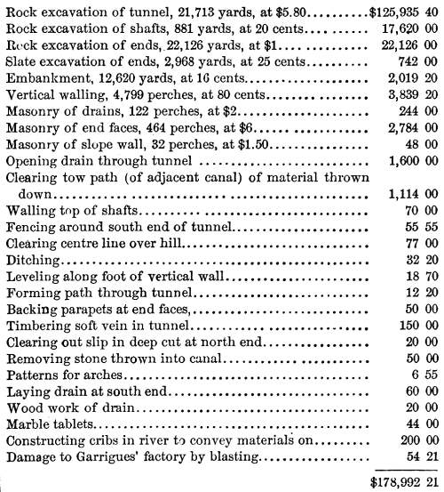
from which we extract the following statement:
Final Estimate of Section 54. James Appleton,
Contractor.
 RAILWAY BRIDGES AND VIADUCTS.
It was manifestly necessary to provide bridges for the passage
of small streams, and even over streams of considerable width,
which were not navigable, bridges were constructed; but over the
early long bridges trains could only be moved at very low rates
of speed, and over some of the navigable streams, now crossed
by many trains daily, ferry-boat operations were continued for
many years.
Stone bridge-building bad been practiced for centuries, and
a number of very durable stone bridges had been erected over minor
streams during the turnpike era. The skill and available force
they developed was pressed into railway service at points where
financial and other considerations permitted. Of one of the early
railway viaducts, built about 1832, which formed part of the Allegheny
Portage Railroad, Mr. Solomon W. Roberts, in 1878, said:—
"The Horseshoe-bend, or Conemaugh viaduct, is still standing,
and is used by the Pennsylvania Railroad Company as a part of
its main line, and it is, I believe, almost the only structure
of the old Portage Railroad now in use. It is a substantial and
imposing piece of masonry, about seventy feet high, and with a
semi-circular arch of eighty-feet span. The chief engineer had
prepared a plan for a bridge of two arches, each of fifty-feet
span, but afterwards adopted the plan of the present structure.
It was designed, and its erection superintended, by me, and the
work was done by an honest Scotch stone-mason, named John Durno,
who was afterward killed by falling from another high bridge.
The arch is three and a half feet thick at the springing line,
and three feet at the crown. The arch stones are of light-colored
sandstone, and the backing of silicious limestone, found near
the spot. The sandstone was split from the erratic blocks, often
of great size, which were found lying in the woods, on the surface
of the ground. The contract price for the masonry was $4.20 per
perch of twenty-five cubic feet, and the work was remarkably well
done. The face stones were laid in mortar made from the silicious
limestones, without the addition of any sand. The cost of the
viaduct was about fifty-five thousand dollars, and by building
it a lateral bend of about two miles was avoided. The embankment
at the end of the viaduct was sixty-four feet high. Since that
work was done, iron bridges have taken the place of such structures."
Of the bridges and viaducts on the Philadelphia and Columbia
Railroad, Mr. W. Hasell Wilson, in his notes on Internal Improvements
in Pennsylvania, says:—
"There were twenty-two railway bridges or viaducts, constructed
with stone abutments and piers, surmounted by timber superstructure;
and thirty-three overhead bridges for public and farm roads.
The following were the most important structures:—
Schuylkill viaduct, having seven spans, the clear lengths of which
between the piers were, two of 122 feet each, three of 135 feet
each, and two of 137 feet each. The abutments and piers were constructed
of coursed and hammer-dressed masonry, from the bottom of the
foundations, which were on rock, with the exception of the western
abutment and two adjacent piers, which were founded upon hard
gravel. Five of the piers were in the river and required coffer
dams; one of them stood in 26 feet depth of water. The wooden
superstructure was 1,045 feet in length by 49 feet in width, with
four trusses on a modification of the Burr plan, having a passage
way of four feet in the middle for foot travelers, and one of
18½ feet on each side for railway and common road respectively.
The height of the bridge floor above ordinary water line was 38
feet.
Valley Creek viaduct consisted of four spans of 130 feet each
in clear, with a height from water to floor of 60 feet.
East Brandywine viaduct had four spans of 89 feet each in clear,
with a height of 30 feet.
West Brandywine viaduct had a length of platform of 835 feet,
divided into six spans, resting upon abutments and piers of coursed
masonry. The railway tracks rested upon the upper chords of the
trusses, at an elevation of 72 feet above the water of the creek.
Pequea viaduct was one span of 130 feet.
Mill Creek viaduct comprised four spans with a total length
of 550 feet, and a height from water to floor of 40 feet.
Little Conestoga viaduct had a superstructure 804 feet in length,
elevated 47 feet above the stream.
All of the above-named bridges were constructed according to
a modification of the Burr plan.
The viaduct over Big Conestoga creek had a superstructure on
the Town lattice plan, 1,412 feet in length, at an elevation of
60 feet above the water line. The spans were of various lengths,
the longest being 120 feet.
The abutments and piers of all the viaducts, except those at
the Schuylkill river and West Brandywine creek, were constructed
of rubble masonry."
BRIDGE CROSSING THE SCHUYLKILL RIVER NEAR PETERS'
ISLAND.
The most important of the bridges referred to above was that
leading from the foot of the inclined plane, on the west bank
of the Schuylkill, to the eastern side of that river, where a
connection was formed with the railway leading to the junction
of Broad and Callowhill streets, in Philadelphia. After being
used as part of the state works from the time of its completion,
in April, 1834, until the construction of a line leading to Market
street, this bridge and its eastern rail connection were sold
to the Philadelphia and Reading Railroad Company, and subsequently
used by that company in facilitating the movement of passenger
and miscellaneous freight trains from the Broad street depot of
its main line. In August, 1886, the receivers of the Philadelphia
and Reading obtained authority to replace this bridge with an
iron structure, to be built by the Phoenix Iron Company. As stated
above, the wooden superstructure, which rendered continuous service
for more than fifty-two years, was built in accordance with a
modification of the Burr plan, and this plan, intermingled with
some modifications, furnished designs for a large proportion of
the important wooden bridges of the period of its erection, as
well as of the wooden bridges built across important streams in
Pennsylvania by turnpike or bridge companies for some years previous
to the commencement of the construction of important railways.
The Schuylkill bridge was designed by Major John Wilson, chief
engineer of the Philadelphia and Columbia Railroad, and the construction
was superintended by Mr. W. Hasell Wilson, principal assistant
engineer. Mr. Frederick Erdman was the bridge inspector, a position
for which he was well qualified by previous experience in the
performance of similar duties for the Schuylkill Navigation Company.
The contractors were Dodd, Bishop & Brittin. The width of
the river at the point of location was about 850 feet, and at
the eastern shore the river was about twenty-five feet deep. As
the bridge possesses great historic interest in this and many
other localities, on account of the important and prolonged service
it has rendered, and as the methods pursued and the items of cost
illustrate more fully than any other attainable data, particulars
relating to important bridge building during the first half of
the fourth decade, in this country, the following extracts from
the note-book of Mr. W. Hasell Wilson, commenced in 1831, are
appended:—
Specifications for the Bridge over Schuylkill
River.
"The bridge is to stand on six piers and two abutments,
which are to be founded on the solid rock, made perfectly level,
and constructed of dressed rubble stone, not less than twelve
inches in thickness, laid in courses. The stones are to be of
the best quality and subject to the inspection of the engineer;
they shall be hammer dressed, squared, and laid in full mortar,
arranged in such manner as to form a system of headers and stretchers
(the headers to be not less than three feet), the filling up to
be of stones of the best quality, properly connected with bond
stones.
[Here follow a number of minute directions relating to the
foundations of the piers, the piers, and abutment walls. The piers
were to be 22 feet thick, and 63 feet 6 inches long at the base,
exclusive of the angular points or heads, which were to extend
from the foundations to high water mark.]
The construction of the wooden superstructure must be in strict
conformity to the plan exhibited by the engineer, the contractor
furnishing all materials, whether of wood or iron. The platform
or floor to be supported by four wooden arches trussed and constructed
as represented in the drawing, placed vertically on the piers
and abutments, at such distances from each other as to admit of
two passages of 18 feet 6 inches each in the clear, and one of
4 feet in the clear, between the arch pieces, which, together
with the thickness of the said trusses, make the whole thickness
of the bridge 49 feet 8 inches. The height of the truss from the
bottom of the chord to the top of the plate is to be 17 feet.
The king-posts are to be 10 x 20 inches above the shoulder, and
10 x 8 inches in the waist, except that part above the arch, which
shall be large enough to saddle 2½ inches on the other
arch pieces. The queen-posts to be of white pine, 10 x 15 inches
above the shoulder, and below the step, and 10 x 9 inches in the
waist, to saddle 2½ inches on the arch pieces, as heretofore
described. The carry braces to be of white pine, 9 x 10 inches.
The stay braces of white pine 5 x 10 inches. The chords of white
pine, 8 x 14 inches, and in such lengths as required by the bill
of timber, furnished by the engineer. The arches of white pine,
8 x 18 inches at the crown, 8 x 24 inches at the foot, placed
on each side of the king-and queen-posts. The plates of white
pine, 10 x 12 inches, the scarfs of which shall not be less than
4 feet long. The girders or floor beams of white pine, 9 x 15
inches, one in every three of which shall pass through the whole
width of the bridge, without scarfing; the ends of the girders
to be secured to the posts by spikes, ¾-inch square, and
15 inches long. The joists of white pine, 5 x 7 inches, placed
at distances of two feet from centre to centre. The floor plank
for side-ways of white pine, 3 inches thick, 19½ feet long,
clear of sap and other defects, about one foot wide; the floor
plank for the middle way 5 feet long, 3 inches thick. The tie-beams,
connecting the plates in upper part of bridge, 6 x 12 inches,
to project one foot over the plates. The side braces of white
oak, 4½ x 5 inches, to be secured by mortices, tenons,
and spikes as the engineer may direct. The horizontal braces in
floor and roof of white pine, 6 x 6 inches, secured ,it each end
or joint by mortices, tenons, and keys. The rafters to be 3 x
5 inches, supported by a ridge plate in centre, and by purlins
and raising plates, 6 inches square. The shingles of Carolina
cedar, 30 inches long, to be dressed and laid on black oak lath,
9 inches to the weather; the outside studding for the reception
of the weather boarding to be of white pine, 3 x 4 inches, placed
2 feet apart from centre to centre, in a perpendicular position.
The weather boards to be of white pine, ¾ inches thick,
put on in regular courses, to be planed on both sides, the studs
also to be planed. Over each end of each pier, the bridge to be
finished with Venetian windows; sky-lights of 4 feet square
to be placed over each side of the roof, in the centre of each
span. All the timbers of the bridge above the floor, except the
upper beams and rafters, to be planed smooth.
From an intermediate point between, and on it line with the
footings of the arches, two braces shall extend to the intersection
of the arches and chords, at which point an iron bar, two inches
square, shall pass through the whole width of the bridge; and
at the footings of said braces upon the pier, together with those
of the arches, cast-iron shoes shall be placed, as represented
in the drawing. At the intersection of the arches and posts, together
with those of the chords and posts, iron screw bolts, 1¼
inches square, are to pass through them, and to be secured by
a nut, worm, and screws. The joints or scarfs of the chords to
be at least four feet long, and secured as represented in the
drawing. Each end of the bridge is to be finished with six Grecian
Doric columns entablature, and pediment, which, together with
the outside of the bridge, shall be painted with three coats of
white lead.
It is understood that all the above work, whether of wood,
stone, or iron, shall be executed in a faithful and workmanlike
manner, without omitting anything which may not have been expressed
in the above specification, and that the bridge, when completed,
shall be in conformity with the plans heretofore referred to.
[Here follows a description of the particulars in which there
had been deviations from the specification. They relate almost
exclusively to the piers, and state that the length of spans in
clear between the footings of arches, commencing at west end of
bridge, was as follows: Nos. 1 and 2, each 122 feet; Nos. 3, 4,
and 5, each 135 feet; Nos. 6 and 7, each 136 feet.]
The foundation of all the piers was solid rock, except two
which rested on hard gravel. Their height varied from 46 feet
to 59-eight-tenths feet.
Final Estimate, Schuylkill Bridge, Dodd, Bishop
& Brittin, Contractors
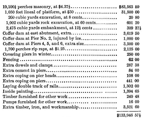
It will be seen that, in contrast with modern prices for similar
work, the bridge was a marvel of cheap construction. The masonry,
costing $4.37½ per perch, could scarcely now be replaced
for less than $15, and the platform, costing $30 per 1,000 lineal
feet, would now probably cost twice that sum. During a series
of years the Philadelphia and Reading made numerous repairs, decaying
or weakening portions of the structure being replaced, but no
material change was made in any of the important features of the
bridge.
TOWN LATTICE BRIDGES.
While work on the Philadelphia and Columbia Railroad was progressing,
the Town lattice plan was attracting an increased degree of attention,
and it was adopted as the superstructure of the viaduct over the
Big Conestoga creek. Its leading merit was relatively small cost,
as thick plank were substituted for heavy timbers. Under ordinary
conditions, it was generally found to possess sufficient strength,
and it was used, during a comparatively brief period, in the progress
of railway construction in Pennsylvania and other states. Its
power to resist some forms of wind pressure, however, was not
fully sufficient, and it was succeeded by more satisfactory methods.
PROTECTION OF WOODEN BRIDGES.
Great importance was formerly attached to the covering of expensive
wooden bridges with a substantial roof which served as a protection.
The passage of locomotives created serious danger of the destruction
of these roofed wooden bridges by fire, and several safeguards
were adopted. One was to employ a watchman, charged with the duty
of passing over a bridge immediately after each train movement,
and he carried a bucket of water in his hand for the purpose of
extinguishing any incipient conflagration. Large tubs or half-hogsheads,
filled with water, were placed at convenient points on each bridge
to serve as reservoirs. Another, which was enforced on the Schuylkill
bridge for a considerable period, was to interdict locomotives,
all cars being drawn over the bridge by horses or mules to and
from the western bank, where the connection with the inclined
plane was made.
DRAW BRIDGES.
A description of the Raritan viaduct on the New Jersey Railroad,
says that it was on Col. Long's plan, 1,700 feet in length, in
spans from 112 to 145 feet reach. Depth of truss, 22 feet; width
between band rails on top, 81 feet; piers, 7 in number, which,
with the two abutments, are faced with sienitic granite. The structure
is of two stories; the lower floor resting upon the bottom of
the trusses, of which there are three, supports a roadway to accommodate
common carriages. The railway reposes on the top of the trusses,
supported by joist bearers 4 feet apart. The chairs, holding the
rails, rest on strong pieces, 4 inches thick by 11 wide, pinned
down to the upper floor, which latter performs the office of a
roof. The braces of the truss framing abut upon pieces of thin
sheet iron, introduced into the points. At a depth of 9 feet from
the tops of the piers and abutments, there is an offset of 9 inches,
upon which are footed the shore braces that assist in supporting
the trusses.
There are four distinct sliding draws, two in each story. The
railroad draws move back into the place of a section which slides
sideways, out of the way, while the common road draws roll on,
opening over the part of the bridge back of them; a movable platform
connecting the draws with the floor of the bridge, being raised
up from it by means of lever beams, when the draw is about to
be opened for the passage of vessels. The spans of the draws are
each 30 feet, and those in the railroad cost $3,000 to $4,000
each.
Transport Systems
| Antebellum RR | Contents
Page
|