The Evolution of the American
Locomotive
Scientific American Supplement—May
1, 1897 (Part 2 of 3)
By Herbet T. Walker
 IN the year 1831 a curious design of locomotive
was introduced by Messrs. Davis & Gartner, of York, Pa. It
was run on the Baltimore and Ohio Railroad. The boiler and cylinders
were upright, with four coupled wheels, 30 in. in diameter, but
it was altered considerably after being placed on the road. The
Atlantic was afterward built by the same firm, and was a much
improved engine. Its boiler and cylinders were also vertical,
beams being used to transmit power to the cranks, which were on
a shaft connected by toothed wheels to an intermediate shaft having
outside cranks coupled to the driving wheels. In consequence of
the peculiar shape and movement of the beams, the engines were
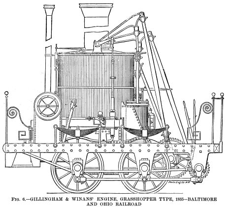
called "Grasshoppers." Fig. 6 shows one of this
class manufactured by Gillingham & Winans for the Baltimore
and Ohio Railroad in the year 1835. Wheels 36 in. in diameter;
boiler 52 in. in diameter, containing 400 tubes 1 in. in diameter
and 3 ft. 2 in. long. Diameter of cylinders 10 in. by 24 in. stroke.
Weight of engine and tender; 7 tons 5 cwt. empty. The circular
structure at the base of the small chimney is a fan which was
driven by the exhaust steam before it escaped. IN the year 1831 a curious design of locomotive
was introduced by Messrs. Davis & Gartner, of York, Pa. It
was run on the Baltimore and Ohio Railroad. The boiler and cylinders
were upright, with four coupled wheels, 30 in. in diameter, but
it was altered considerably after being placed on the road. The
Atlantic was afterward built by the same firm, and was a much
improved engine. Its boiler and cylinders were also vertical,
beams being used to transmit power to the cranks, which were on
a shaft connected by toothed wheels to an intermediate shaft having
outside cranks coupled to the driving wheels. In consequence of
the peculiar shape and movement of the beams, the engines were
called "Grasshoppers." Fig. 6 shows one of this
class manufactured by Gillingham & Winans for the Baltimore
and Ohio Railroad in the year 1835. Wheels 36 in. in diameter;
boiler 52 in. in diameter, containing 400 tubes 1 in. in diameter
and 3 ft. 2 in. long. Diameter of cylinders 10 in. by 24 in. stroke.
Weight of engine and tender; 7 tons 5 cwt. empty. The circular
structure at the base of the small chimney is a fan which was
driven by the exhaust steam before it escaped.
This fan was for urging the fire. It was, however, subsequently
removed and the exhaust steam turned into the large chimney in
the usual way. This engine and seven other similar ones were in
constant service on the Baltimore and Ohio Railroad for a period
of over fifty years. Some of them are now in the Field Museum.
Fig. 7 shows the celebrated John Bull, which is now
in the National Museum, Washington, D. C. It was the first engine
for the Camden and Amboy Railroad, now a part of the Pennsylvania
Railroad. It was designed and built by Stephenson & Company,
of Newcastle upon Tyne. This engine represents another step in
locomotive construction, for while it somewhat resembles the De
Witt Clinton, the cylinders are placed at the smoke box end of
the engine, and the smoke box is of the same pattern as used to-day;
both these improvements were embodied in the before mentioned
Planet engine designed by Stephenson early in the year 1830.
This engine (John Bull) was ordered by Robert L. Stevens, President
of the Camden and Amboy Railroad, from Messrs. Stephenson &
Company, in December, 1830, and was shipped to Bordentown, N.
J., where it arrived in August, 1831. The cut (Fig. 7)
was made from a drawing now in the Washington Museum, and is said
to be an exact representation of the engine when it arrived in
this country; but in a copy of one of Stephenson's working drawings
in the author's possession the engine is shown with a chimney
of different shape and with a different arrangement of safety
valves. This matter is small in itself, but illustrates one of
the many difficulties that confront a writer who undertakes to
show and describe locomotives built so many years ago.
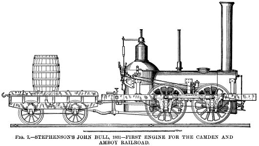 The engine was originally named Stevens, but
on its arrival in this country the railroad company called it
John Bull, and it was entered in their books as "No. 1."
It was put in service November 12, 1831, at Bordentown, N.J.,
where the Railroad Monument now stands. The leading dimensions
were as follows: The engine was originally named Stevens, but
on its arrival in this country the railroad company called it
John Bull, and it was entered in their books as "No. 1."
It was put in service November 12, 1831, at Bordentown, N.J.,
where the Railroad Monument now stands. The leading dimensions
were as follows:
Weight about 10 tons, boiler, 3 ft. 6 in. diameter; cylinders,
9 in., diameter by 20 in. stroke. Four coupled wheels 4 ft. 6
in. diameter, with cast iron hubs and locust wood spokes and felloes.
Tires of wrought iron ¾ in. thick; sixty-two tubes, 7 ft.
6 in. long by 2 in. diameter. Furnace 3 ft. 7 in. long by 3 ft.
2 in. high (for burning wood). Heating surface of tubes, 213 sq.
ft.; of firebox, 36 sq. ft. Total heating surface, 249 sq. ft.
The firebox was of the dome or Bury pattern. The reversing gear
was complicated, the two eccentrics being secured to a sleeve
or barrel, which fitted loosely on the crank shaft. A treadle
was used to change the position of this loose eccentric sleeve,
moving it to the right or left lengthwise on the shaft. Two carriers
were secured firmly to the shaft (one on each side of the eccentrics);
one carrier worked the engine ahead, the other back, so that when
the eccentrics were half way between the two carriers, the axle
turned without moving them, and the engine was out of gear. In
order to reverse, the engine driver placed his foot on the treadle
(which is between the firebox and the handle of the feed water
cock), thereby disengaging the eccentrics from the carriers he
then pulled a small handle on the right side of the boiler and
so lifted the small ends of the eccentric rods (which passed forward
to the rocking shaft on the front of the engine) clear of the
valve stems, after which he took hold of the two valve levers
on the foot plate, and by moving them back and forth admitted
steam to the cylinders by the hand gear; when the engine was fairly
started, he, by means of the treadle, caused the eccentrics to
engage with the opposite carrier, and it continued to actuate
the valves.
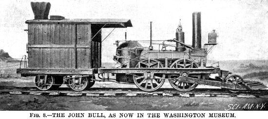 Soon after the engine arrived, the Camden
and Amboy mechanics made the following changes and additions:
As the railroad curves were very sharp, the coupling rods and
cranks were removed and a lateral play of 1½ in. given
to the leading axle, to which a cowcatcher was connected. The
wooden wheels were replaced by cast iron wheels. The dome was
moved forward to the former man hole and the boiler lagged with
wood. A bell was placed on the boiler and a headlight on the smoke
box. A new tender was subsequently built, having a small cab on
the rear for the accommodation of a brakeman, who, if anything
went wrong with the cars, could signal the engine driver to stop.
The engine then presented the appearance shown in Fig. 8.
From a cut in the Railroad Gazette of March 9, 1877. it appears
that a cab and a large wood-burning chimney were subsequently
added, but both these were removed some time before the engine
was placed in the United States National Museum. Soon after the engine arrived, the Camden
and Amboy mechanics made the following changes and additions:
As the railroad curves were very sharp, the coupling rods and
cranks were removed and a lateral play of 1½ in. given
to the leading axle, to which a cowcatcher was connected. The
wooden wheels were replaced by cast iron wheels. The dome was
moved forward to the former man hole and the boiler lagged with
wood. A bell was placed on the boiler and a headlight on the smoke
box. A new tender was subsequently built, having a small cab on
the rear for the accommodation of a brakeman, who, if anything
went wrong with the cars, could signal the engine driver to stop.
The engine then presented the appearance shown in Fig. 8.
From a cut in the Railroad Gazette of March 9, 1877. it appears
that a cab and a large wood-burning chimney were subsequently
added, but both these were removed some time before the engine
was placed in the United States National Museum.
As far as the writer can discover, this was the first engine
equipped with a bell, headlight and cowcatcher, although bells
were used on English locomotives as far back as 1827.
This remarkable locomotive was exhibited at the Philadelphia
Exposition of 1876, and again at the Chicago Exposition of Railway
Appliances in 1883, and lastly, at the Columbian Exposition of
1893. Leaving New York City under steam April 17, 1893, it hauled
"the John Bull train" of two cars 912 miles, without
assistance, to Chicago, arriving April 22, and meeting with continued
ovation over the entire route. It formed part of the Pennsylvania
Railroad Company's exhibit, and was one of the great attractions
of the World's Fair, carrying over fifty thousand passengers over
the exhibition tracks in the terminal station yard. The engine
left Chicago again under steam December 5, 1893, coming east over
the Pennsylvania lines via the Southwest system to Pittsburgh,
and through Altoona, Harrisburg and Baltimore to Washington, arriving
there December 13, 1893. This was a very good performance for
a locomotive sixty-two years of age. It was then returned to the
museum at Washington, where it will remain permanently.
In the year 1832, William T. James, of New York, invented a
very important improvement in locomotive valve gear, viz., the
link motion. This reversing and expansion gear is the embodiment
of "the beauty of simplicity," for, while the valve
gears up to that time and for years afterward were largely made
up of a complication of rods and levers, as in the John Bull,
they only served to reverse the engine and did not admit of the
steam being worked with a varying degree of cut-off and expansion,
so essential to the economical working of a locomotive. James'
design was nothing more nor less than connecting the small ends
of the fore and back gear eccentric rods by a curved link, the
curve being concave toward the eccentrics, said link having a
slot which engaged a slide block, fastened to the valve stem.
By a hand lever the engine driver could move the link up or down,
thus causing either the fore or back gear eccentric to communicate
motion to the slide valve and so control the direction of the
engine's motion.
The effect of this device as a cut-off mechanism is that when
the slide block is in the center of the link, midway between the
two eccentric rods, the engine will be in midgear, but on the
link being moved so as to bring one of the eccentric rods—say
the fore gear rod—opposite to the block, and steam being
admitted, the engine will move forward and the valve will cut
off the steam when the piston is nearly at the end of its stroke;
if the link is moved so that the block will occupy a position
between the eccentric rod and the center of the link, the slide
valve will cut the steam off at an earlier period of the piston's
stroke and so leave the rest of the stroke to be performed by
the expansion of the steam, and the more nearly the center of
the link is brought to the slide block the shorter becomes the
travel of the valve and the earlier will the steam be cut off.
Thus, the rate of cut-off and degree of expansion, either for
fore or back gear, can be regulated while the engine is running
and according to the work it has to do.
This is one of the simplest inventions in the world. There
is no valve gear equal to it, and it is used on nearly every locomotive
to-day.
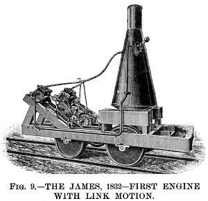 James' engine of 1832 (see Fig. 9),
fitted with the link motion, was intended for the Baltimore and
Ohio Railroad. The boiler was vertical and of weak construction.
The cylinders were 8 in. in diameter by 12 in. stroke and the
slide valves had ½ in. lap at each end. The gross weight
was 3½ tons. There were four wheels (not coupled) 3 ft.
in diameter. James' engine of 1832 (see Fig. 9),
fitted with the link motion, was intended for the Baltimore and
Ohio Railroad. The boiler was vertical and of weak construction.
The cylinders were 8 in. in diameter by 12 in. stroke and the
slide valves had ½ in. lap at each end. The gross weight
was 3½ tons. There were four wheels (not coupled) 3 ft.
in diameter.
A representative of the American Railroad Journal visited Mr.
James' shop at 40 Eldridge Street, New York City, to examine his
wonderful locomotive which had just been completed. He states
that the engine was run on a track fifty feet in length, backward
and forward eight times in 63 seconds, including stops: Although
he does not describe the valve motion, it is evident that none
but the most efficient reversing gear, such as the link motion
is, would have secured such a result. He also states that Mr.
James (a few days later) placed the engine on wheels without flanges
and ran it over the pavements and Third Avenue to Yorkville, about
five miles, where he took breakfast and then returned to the city.
[American Railroad Journal, October 29, 1832.]
It may be mentioned that a weight, which can be seen in Fig.
9, was fixed on the reversing lever to retain the links in
position for fore or back gear, there being no means of fixing
them in an intermediate position; but Mr. Samuel B. Dougherty
(subsequently locomotive superintendent of the Camden and Amboy
Railroad), who assisted in the construction of this engine, and
wrote a description of it in May; 1858, said that "in setting
the eccentrics we found the link would cut off, and we so used
it on the engine to expand from different points." [Colburn's
Locomotive Engineering and Mechanism of Railways, 1871.]
Before this engine was sent to Baltimore it was run for some
time on the Harlem Railroad, where it worked satisfactorily. In
1833 it was forwarded to its destination, but, soon after having
been placed in regular service, the boiler exploded and the engine
was totally destroyed. A full size model of this engine was sent
to the Columbian Exposition.
Strange to say, the link motion after this appears to have
dropped out of sight, American engineers using a variety of fork
or hook motions, all more or less objectionable, until ten years
later, when we will again take the matter up in its chronological
order.
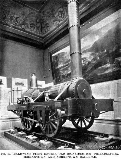 In the year 1832, Matthew W. Baldwin, founder
of the famous Baldwin Locomotive Works, received an order for
a locomotive from the Philadelphia, Germantown and Norristown
Railroad Company, whose short line of six miles was operated by
horse power. He, in company with his friend, Mr. Peale, went to
Bordentown to examine one of Stephenson's engines (probably the
John Bull) on the Camden and Amboy Railroad, and made some memoranda
of its principal dimensions. After many difficulties had been
surmounted, he built a locomotive and christened it Old Ironsides.
It was tried on the road November 23, 1832, and is shown in Fig.
10. In the year 1832, Matthew W. Baldwin, founder
of the famous Baldwin Locomotive Works, received an order for
a locomotive from the Philadelphia, Germantown and Norristown
Railroad Company, whose short line of six miles was operated by
horse power. He, in company with his friend, Mr. Peale, went to
Bordentown to examine one of Stephenson's engines (probably the
John Bull) on the Camden and Amboy Railroad, and made some memoranda
of its principal dimensions. After many difficulties had been
surmounted, he built a locomotive and christened it Old Ironsides.
It was tried on the road November 23, 1832, and is shown in Fig.
10.
A full size model of this engine is now in the Field Columbian
Museum, Chicago. Its chief dimensions were as follows: Driving
wheels, 4 ft. 6 in. diameter; leading wheels, 3 ft. 9 in. diameter;
cylinders, 9½ in. in diameter by 18 in. stroke. They were
attached horizontally to the outside of the smoke box, just inside
the frames, which were of wood, with iron pedestals. The wheels
were made with heavy cast iron hubs, wooden spokes and rims, and
wrought iron tires. The boiler was 30 in. in diameter, and contained
72 copper tubes 1½ in. diameter and 7 ft. long. The reversing
gear consisted of a single eccentric, with a double latch eccentric
rod gearing alternately on pins on the upper and lower ends of
the arms of a rocking shaft. It will be seen that the Ironsides
closely
resembled the John Bull, except that the leading wheels were
smaller than the driving wheels, and the firebox was of the regular
Stephenson type instead of the dome or Bury pattern.
This engine weighed about 8 tons and was able to draw 30 tons
on a level. It was the first locomotive Mr. Baldwin ever built,
and did duty on the Germantown and other roads for over a score
of years, and was seen by Zerah Colburn at the Fitchburg Railroad
station, Boston, in 1853. It is but justice to Baldwin to add
that he soon abandoned the English design of the Ironsides and
quickly placed himself at the front in American locomotive practice,
some of the finest engines in their day having been built by him.
American designs very soon began to depart from their British
prototypes, and a process of adaptation to the existing conditions
of the railroads in this country followed.
Until recently, a marked feature of difference between American
and English locomotives has been the use of the swiveling truck
under the former to facilitate the passage of the engine around
curves. An English patent dated December 30, 1812, was granted
to William and Edward Chapman for a four wheeled swiveling truck.
In the year 1815, Messrs. Blackett & Hedley constructed a
locomotive named Puffing Billy for the Wylam Colliery Railway,
having two four wheeled trucks, but the truck did not come into
general use in England until about thirty years ago.
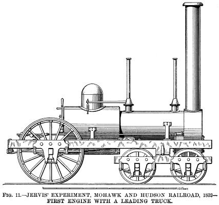 In the year 1831 Mr. Horatio Allen designed
an engine with two trucks for the South Carolina Railroad, of
which he was then the chief engineer, but to Mr. John B. Jervis,
chief engineer of the Mohawk and Hudson Railroad, belongs the
honor of designing the first engine with a leading truck swiveling
on a center pin, as generally used the world over to-day. This
was in the year 1831; and in the year 1832 his engine Experiment
was put on the above named road for regular service. The cylinders
were 9-and-five-eighths in. in diameter by 16 in. stroke. Diameter
of driving wheels, 5 ft. Grate 5 ft. long, for burning anthracite
coal. Weight 7½ tons. This important locomotive is shown
in Fig. 11. It was the ordinary uncoupled or single driving
wheel engine as commonly used at that period, and, as it presents
no novel features aside from the truck, further description is
unnecessary. [An interesting letter from Mr. Jervis, with an illustration
of his Experiment, appeared in the Railroad Gazette, Vols. III
and IV.] In the year 1831 Mr. Horatio Allen designed
an engine with two trucks for the South Carolina Railroad, of
which he was then the chief engineer, but to Mr. John B. Jervis,
chief engineer of the Mohawk and Hudson Railroad, belongs the
honor of designing the first engine with a leading truck swiveling
on a center pin, as generally used the world over to-day. This
was in the year 1831; and in the year 1832 his engine Experiment
was put on the above named road for regular service. The cylinders
were 9-and-five-eighths in. in diameter by 16 in. stroke. Diameter
of driving wheels, 5 ft. Grate 5 ft. long, for burning anthracite
coal. Weight 7½ tons. This important locomotive is shown
in Fig. 11. It was the ordinary uncoupled or single driving
wheel engine as commonly used at that period, and, as it presents
no novel features aside from the truck, further description is
unnecessary. [An interesting letter from Mr. Jervis, with an illustration
of his Experiment, appeared in the Railroad Gazette, Vols. III
and IV.]
As time went on, it was found that one pair of driving wheels
did not furnish sufficient adhesion and power for the ever increasing
loads to be hauled, and, therefore, the next step was to utilize
the four coupled wheels embodied in some of the engines previously
illustrated and combine them with the leading truck. This arrangement
was patented in 1836 by Henry R. Campbell, chief engineer of the
Germantown Railroad, "in order to distribute the weight of
the engine upon the rails more completely." In the same year
he designed the freight engine shown in Fig. 12 (the previous
engines were used for both freight and passenger trains), and
thus we have the first American eight wheeled engine. It had cylinders
14 in. diameter by 16 in. stroke. Driving wheels 4 ft. 6 in. diameter,
the forward pair being without flanges. Gross weight about 12
tons, the adhesive weight being 8 tons. Heating surface about
725 sq. ft. It was tried on the Philadelphia and Germantown Railroad,
May 8, 1837, but was found to be a "hard rider," for
the reason that it had no means of equalizing the weight on the
driving wheels so as to meet the various undulations in the track,
and it would also appear from the drawing that the truck had no
center pivot, the frame being made with 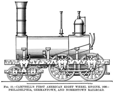 vertical
projections sliding in pedestals on the main frame, and being
connected thereto by side springs. If this was the case, the truck
could only vibrate in a vertical plane and could not turn horizontally.
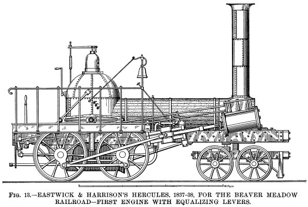
To remedy the defects of the Campbell engine, Messrs. Garret &
Eastwick, of Philadelphia, completed in 1837 a new style of freight
locomotive for the Beaver Meadow (now the Lehigh Valley) Railroad
Company. This engine, named Hercules, had a separate rectangular
frame for the four coupled wheels, this frame being pivoted on
each side to the main frame by springs and journal boxes sliding
vertically in pedestals on the main frame. Thus the separate frame
was enabled to move up and down as well as to swing vertically
on its center, and so permit the four driving wheels to accommodate
themselves to the unevenness of the track, provided the undulations
were alike on both rails, which of course, never happened, and
the "separate frame" got badly racked in consequence. vertical
projections sliding in pedestals on the main frame, and being
connected thereto by side springs. If this was the case, the truck
could only vibrate in a vertical plane and could not turn horizontally.
To remedy the defects of the Campbell engine, Messrs. Garret &
Eastwick, of Philadelphia, completed in 1837 a new style of freight
locomotive for the Beaver Meadow (now the Lehigh Valley) Railroad
Company. This engine, named Hercules, had a separate rectangular
frame for the four coupled wheels, this frame being pivoted on
each side to the main frame by springs and journal boxes sliding
vertically in pedestals on the main frame. Thus the separate frame
was enabled to move up and down as well as to swing vertically
on its center, and so permit the four driving wheels to accommodate
themselves to the unevenness of the track, provided the undulations
were alike on both rails, which of course, never happened, and
the "separate frame" got badly racked in consequence.
To overcome this objection, Mr. Joseph Harrison, Jr., of the
firm of Eastwick & Harrison, patented in 1838 an improvement
for equalizing the weight on the wheels of locomotive engines.
The preferred form consisted in placing the driving axle bearings
in pedestals on the main frame in the usual manner (the separate
frame being discarded), and, instead of connecting the driving
wheel axle boxes directly to the frame by springs (as in Campbell's
engine), a horizontal beam or lever was introduced, having a central
pivot linked to a spring fastened to the frame, and its ends provided
with rods that passed down through the frame and abutted on said
axle boxes. There were two of these levers, one on each side of
the engine. They vibrated separately and thus met all the unevenness
in both rails. In all equalized engines now built in this country
or in Europe this device of Mr. Harrison's is used in one or other
of the different ways indicated in his patent. [The Locomotive
Engine, by Joseph Harrison, Jr.]
These compensating levers are known as equalizers, because'
when running on an uneven track, they distribute the shock or
jar equally over all the wheels so connected.
Fig. 13 is a side elevation of this important engine
as rearranged with Harrison's equalizing levers, and a full size
model of it is now in the Field Museum, Chicago. The engine had
12 in. cylinders by 18 in. stroke, and four coupled driving wheels
3 ft. 8 in. diameter. Its gross weight was about 14 tons, of which
9 tons were available for adhesion. With steam of 90 lb. pressure
per square inch (then a common pressure in this country) the engine
drew a load of 265 tons, including the tender, up a grade varying
from 27 ft. to 35 ft. per mile. The speed was not given, but the
other particulars are derived from the report of a committee of
the Franklin Institute, dated May 9, 1839.
 While there is no doubt that Harrison was
the original inventor of equalizing levers as used at the present
day, it is necessary to call attention to the fact that Timothy
Hackworth (Stephenson's great rival) rebuilt a six coupled engine,
named Royal George, for the Stockton and Darlington Railway, in
the year 1827; each of the middle and back wheels were equalized
by a spring in the same way as shown in Fig. 2 of Harrison's specification
above referred to. A drawing of the Royal George will be found
in Colburn's Locomotive Engineering and Mechanism of Railways,
page 21. While there is no doubt that Harrison was
the original inventor of equalizing levers as used at the present
day, it is necessary to call attention to the fact that Timothy
Hackworth (Stephenson's great rival) rebuilt a six coupled engine,
named Royal George, for the Stockton and Darlington Railway, in
the year 1827; each of the middle and back wheels were equalized
by a spring in the same way as shown in Fig. 2 of Harrison's specification
above referred to. A drawing of the Royal George will be found
in Colburn's Locomotive Engineering and Mechanism of Railways,
page 21.
Before dismissing the Hercules, we will notice the reversing
gear, which was patented by Mr. A. M. Eastwick, July 21, 1835,
and is very simple and ingenious. It will be seen by Fig. 13
that the valve chest had two valve stems projecting therefrom.
The upper one was for the ordinary slide valve and was connected
to a rocking shaft actuated by a single eccentric on the rear
axle. The lower one was connected to a movable block working between
the slide valve and the cylinder ports. This movable block had
four ports, two for fore gear and two for back gear. The fore
gear ports (called direct ports) opened directly into the cylinder
in the usual way, but the back gear ports (called indirect ports)
went but half way through the block, and then turned and passed
each other before entering the cylinder. When it was desired to
run the engine backward, the block was moved by the hand lever
on the foot plate to bring the indirect ports in communication
with the cylinder, so that when the slide valve admitted steam
to the front port in the block it was conducted to the back end
of the cylinder and vice versa. A similar device was patented
in England by William Beckett Johnson in the year 1847.
It is interesting to note that Mr. Harrison, in conjunction
with Mr. Winans, afterward constructed and worked the rolling
stock of the St. Petersburg and Moscow Railway in Russia, and
all the engines, nearly 200 in number, originally made at Alexandrowski,
near St. Petersburg, were fitted with Eastwick's reversing valve
block, and, with the addition of a separate expansion valve, these
engines were running as late as the year 1871.
(To be continued.)
Antebellum RR
| Contents Page
|