 IMPROVEMENTS IN THE CABLE RAILWAY IMPROVEMENTS IN THE CABLE RAILWAY
OF THE NEW YORK AND BROOKLYN BRIDGE.
Scientific American—
July 21, 1888
Our readers who have not seen the great East River Bridge which
connects New York and Brooklyn have been made familiar with its
appearance and the details of its construction through the frequent
and profusely illustrated articles on the subject which have appeared
in these columns from time to time. It is not necessary, therefore,
to go into minutiæ regarding the structure itself, but it
will, perhaps, be well to repeat in brief some of the dimensions
of the bridge, and give some facts regarding the traffic.
The bridge is 5,989 feet long, 85 feet wide, supported by four
15¾ inch wire cables. It is divided into five longitudinal
divisions: the carriage ways being at the outside, the elevated
promenade in the middle, and the two railways between the promenade
and the carriage ways. An endless cable, 1½ inches in diameter,
extends from the engine house in Brooklyn over sheaves at the
center of the railway track to the New York terminus, thence across
underneath the New York approach to the other railway, returning
in the same manner.
The propelling plant, which has been in use upon the bridge
from the day of its opening up to the present time, consisted
of two horizontal steam engines, each having a cylinder 26 inches
in diameter, a stroke of 48 inches, with a fly wheel 18 feet in
diameter, weighing 30,000 pounds. These engines have been operated
one at a time, jaw clutches being provided for throwing one or
the other of the engines into gear with the cable drums, as required.
The entire traffic of the railway has been carried on by means
of 3-car trains, propelled by these engines through the medium
of the cable.
Since the completion of the bridge, the growth of the traffic
has been so regular and so rapid as to render apparent the necessity
of increasing the carrying facilities. In April, 1884, 752,220
passengers were carried over the bridge. In April, 1888, 2,593,104
passengers were carried. If the traffic were evenly distributed
through the day, the 3-car trains could readily carry the passengers
for some time to come; but, as is well known, the traffic varies
greatly with different hours of the day. For example: in the hour
beginning at 8 o'clock in the morning, from 10,000 to 12,000 people
are carried from Brooklyn to New York, while less than 1,000 are
carried from New York to Brooklyn. In the hour beginning at 5
o'clock in the afternoon, from 9,000 to 10,000 people are carried
from New York to Brooklyn, while only about 1,500 are carried
at the same hour from Brooklyn to New York. In the middle of the
day the average in either direction is about 2,000 per hour, and
at midnight scarcely more than one-tenth of that number.
This enormous traffic exceeds the original expectations, and the
great and abrupt fluctuations of power required to propel the
trains at these busy hours have severely tested the engines. One
day's record showed that the power ranged from 303 h.p., as a
maximum to 129 h.p. negative, as a minimum. We are informed of
one instance in which there was an increase of 190 h.p. within
15 minutes, and another in which the power was increased by 239
h.p. within 80 minutes.
To provide economically for the present traffic, to anticipate
future increase, as well as to provide for various improvements
which have been developed by conditions peculiar to this particular
railway, and to guard against any suspension of traffic by any
possible accident to a part of the machinery, a new driving plant
has been constructed and put in operation.
The old machinery is located in one of the arches of the approach
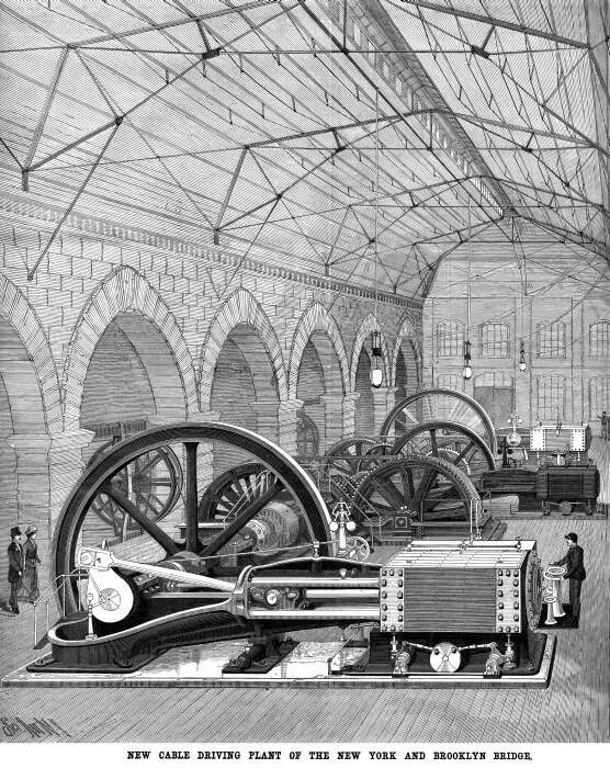
adjoining the Brooklyn station. The engines of the new plant are
contained by a substantial brick building adjoining the north
side of the approach, and abutting against the boiler house. In
this building are placed three magnificent engines, built by William
Wright, of Newburg, New York. They are of the girder type, of
graceful design and elegant finish. These engines are placed parallel
with each other, and arranged to be coupled independently with
the cable drums. They are of three sizes; the largest one (625
h.p.), for propelling the trains at night and morning, has a cylinder
30 inches in diameter, with a stroke of 48 inches; the next in
size (400 h.p.) has a cylinder of 26 inches in diameter, with
a stroke of 48 inches; the smallest one (275 h.p.) has a cylinder
of 22 inches in diameter, with a stroke of 36 inches. The fly
wheel of the largest engine is 20 ft. in diameter, and weighs
50,000 lb.; the fly wheel of the next is 20 ft. in diameter, and
weighs 40,000 lb.; and the fly wheel of the smallest engine is
15 ft. in diameter, and weighs 16,000 lb. The smallest engine
is connected with the driving shaft by means of gearing and clutches;
the larger engines are connected direct by means of clutches.
The driving shaft is made in sections, and arranged to be connected
by jaw clutches and friction clutches, so that either of the engines
may be brought into connection with either pair of cable drums.
Each engine is provided with a friction clutch by which it may
be thrown into engagement with the driving shaft while the cable
and driving machinery is in motion, so that the engines may be
shifted without loss of time.
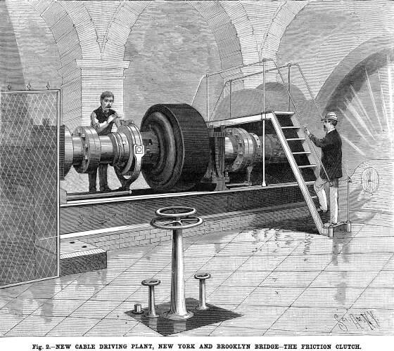 One of these ponderous clutches
is shown in Fig. 2. In the foreground of the picture may be seen
the usual column and throttle valve wheel for starting and stopping
the engine; also another wheel arranged upon a hollow shaft inclosing
the throttle valve spindle, and connected with the clutch-operating
mechanism. The operation of shifting the engines consists in starting
the engine by means of the throttle valve in the usual way, and
when the engine attains its normal speed, throwing in the clutch
by means of the clutch-operating wheel, then disconnecting the
clutch of the engine to be taken off. One of these ponderous clutches
is shown in Fig. 2. In the foreground of the picture may be seen
the usual column and throttle valve wheel for starting and stopping
the engine; also another wheel arranged upon a hollow shaft inclosing
the throttle valve spindle, and connected with the clutch-operating
mechanism. The operation of shifting the engines consists in starting
the engine by means of the throttle valve in the usual way, and
when the engine attains its normal speed, throwing in the clutch
by means of the clutch-operating wheel, then disconnecting the
clutch of the engine to be taken off.
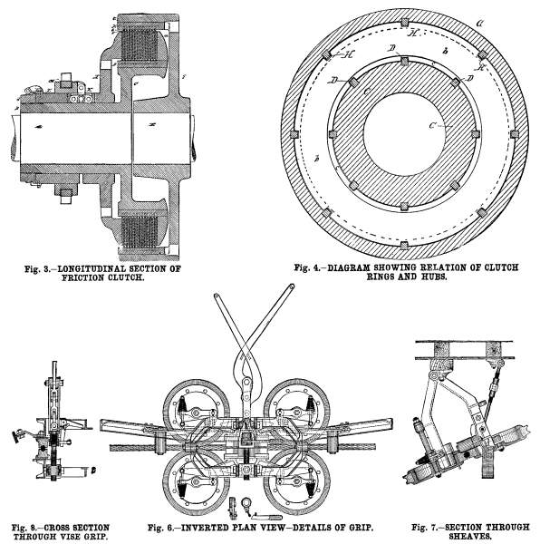
The details of the friction clutch are shown in Figs. 3 and
4, Fig. 3 being a longitudinal section of a clutch and Fig. 4
a diagram showing the relation of the clutch rings. To the engine
shaft, A, is attached a sleeve, B, provided with a hub, C, which
supports the friction rings, b c, the hub being provided
with a flange, a, forming an abutment for the friction
rings. In the hub, C, are inserted eight feathers, D. The rings,
b c, are of two diameters, the rings, b, of smaller
diameter being slotted to receive the feathers, D. The rings,
c, which are of larger diameter, are slotted in their peripheries
to receive eight feathers, H, inserted in the rim, G, of, the
hub, F, secured on the shaft, E. By this arrangement, it will
be noticed that all of the rings, b, must turn with the
hub, F, and all of the rings, c, must turn with the hub,
C.
Upon the sleeve, B, is placed a clamping collar, I, which is
capable of being forced into contact with the series of rings,
b c, clamping them tightly against the flange, a.
 On the sleeve, B, is placed a
sleeve, L, which abuts against an adjusting ring, d, screwed
on the end of the sleeve, B. The sleeve, L, forms an abutment
for toggles, K, three in number, which serve to force the clamping
collar, I, into contact with the rings, b c. On the sleeve,
L, is placed a grooved ring, M, arranged to work the toggles,
K, and in the groove of the ring, M, is placed a strap, which
is connected through a system of levers with the clamping wheel
before referred to. A is the driven shaft, E the driver. When
the toggles, K, are loosened, the shaft, E, turns independently
of the shaft, A; but when the toggles are straightened, bringing
the friction rings, b c, into forcible contact with each
other, the shaft, E, will carry the shaft, A. On the sleeve, B, is placed a
sleeve, L, which abuts against an adjusting ring, d, screwed
on the end of the sleeve, B. The sleeve, L, forms an abutment
for toggles, K, three in number, which serve to force the clamping
collar, I, into contact with the rings, b c. On the sleeve,
L, is placed a grooved ring, M, arranged to work the toggles,
K, and in the groove of the ring, M, is placed a strap, which
is connected through a system of levers with the clamping wheel
before referred to. A is the driven shaft, E the driver. When
the toggles, K, are loosened, the shaft, E, turns independently
of the shaft, A; but when the toggles are straightened, bringing
the friction rings, b c, into forcible contact with each
other, the shaft, E, will carry the shaft, A.
The capacity of the clutch is increased by increasing the number
of the rings, b c. The clutch for the large 625 horse power
engine has 27 rings, the clutch for the 400 horse power engine
has 19 rings, and the clutch for the 275 horse power engine has
13 rings.
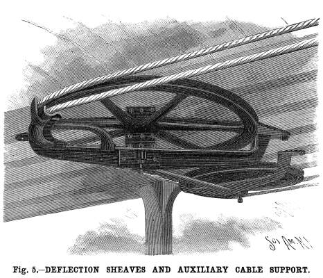
To guard against every possible emergency, all the important
parts of the machinery have been made in duplicate. There are
two sets of driving drums, two cables, one in motion and the other
in reserve. The cable running out from the engine house passes
over the deflection sheaves around sheaves carried by the tension
car, thence outward, and the incoming or hauling end of the cable
passes around a set of deflection sheaves, thence downward underneath
the upper floor of the Brooklyn station to a large sheave revolving
in a horizontal plane, and shown in Fig. 5, thence back to the
propelling drums. The second cable, which is held in reserve,
passes around an extra set of propelling drums and is supported
near the sheaves, in readiness to be transferred to them in case
of necessity. The transfer of cables requires about one hour,
and while it is being done the trains are carried over the bridge
by locomotives.
 The grip now used is shown in
Figs. 6 to 8 inclusive; Fig, 6 being an inverted plan view, Fig.
7 a section through the sheaves, and Fig. 8 a central cross section. The grip now used is shown in
Figs. 6 to 8 inclusive; Fig, 6 being an inverted plan view, Fig.
7 a section through the sheaves, and Fig. 8 a central cross section.
In the grip there are four sheaves placed in pairs, so that the
cable is gripped between each pair. Each sheave has a heavy grooved
rim with a cylindrical inner surface against which the brake presses.
The rim is in. two parts bolted together, and holds in a dovetail
groove a packing of leather and India rubber belting in alternating
pieces placed radially. The packing projects well out of the rim,
and is grooved to receive the cable.
There are four brakes, one for each sheave. They are made of
hard wood, with a curved outer face fitted to the inside of the
rim of the sheave.
The main frame of the grip is in two parts, each hinged in
a common line parallel to the cable, close under the car floor,
one part hanging on each side of the cable. The sheaves are each
carried by a small frame hinged to the main frame, on a line parallel
to the shaft of the sheave. This small frame has a limited movement
opposed by a coiled spring which tends to force the sheave away
from its brake. Each of the four brakes is held by a projecting
end of the main frame. The upper part of the main frame, from
which the operating levers project, is fixed in position by adjustable
stay rods. The movable part is connected to the operating levers
by a coarse-threaded screw which is turned by a ratchet wheel
and pawl.
As the grip is used the packing in the grooves of the sheaves
is slowly compressed and worn, thereby permitting the sheaves
to come more nearly together as the grip is closed, and the short
arms of the operating levers approach more closely to a straight
line, and as this continues, the pressure on the packed surfaces
increases rapidly. Such action is prevented, when, as the grip
is closed, a certain position of the levers in approaching each
other is passed, by the pawl engaging with the tooth of the ratchet
wheel, then, as the levers are separated, the screw is turned
slightly, bringing the sheave surfaces and levers to their former
and normal relative positions. As the grip is closed and the sheaves
are brought into contact with the cable, they are revolved at
cable speed, the car being at rest. As power is applied to the
brakes, the sheaves are forced together with an increasing pressure,
which is transmitted from the brakes to the sheaves, developing
a frictional resistance which tends to prevent the sheaves from
revolving. This action continues until the resistance in the four
sheaves exceeds the tractive resistance of the car, when the sheaves
cease to revolve and the car moves at cable speed.
The vise grip (which grasps the cable only as the frames and
sheave packing yield) is intended to take full hold after the
sheaves cease to revolve and the car is moving at cable speed.
To the frame holding the grip is applied an inverted rail,
which comes into contact with flat-faced pulleys on the tilting
frames of the sheaves which support the cable. This inverted rail
causes the movable sheaves to hold the cable at the proper height
to be received by the grip. The packing of the grips and sheaves
forming the contact surface for the cable is made of alternating
pieces of leather and India rubber. The packing is cut by machinery
and the pieces are put together under pressure. The composite
nature of the packing allows the leather to swell when moist and
to shrink when dry, the elasticity of the rubber keeping the packing
in proper shape.
Besides the hand brakes with which each car is provided, there
are vacuum brakes operated by connection with reservoirs carried
by the cars and exhausted of air by pumps operated by the eccentrics
on the car axles. The brakes have proved very efficient, the vacuum
being readily maintained by the pumps.
In the reconstruction of the propelling plant of the bridge
great credit is due to Mr. C. C. Martin, chief engineer and superintendent,
and to Mr. G. Leverich, assistant engineer, who have given to
every detail of the new plant the utmost care and attention. Nothing
has been omitted which would increase the efficiency of the machinery.
On the other hand, nothing has been introduced that is without
a practical bearing. The entire work has been done from plans
and specifications furnished by the engineers. The engines were
made by Mr. Wm. Wright, of Newburg, N. Y., as already stated.
The cable drums and machinery are from the works of the Southwark
Foundry and Machine Co., Philadelphia, Pa., and the clutches,
including their operating gear, from the works of Poole &
Hunt, of Baltimore, Md.
Brooklyn Bridge | Bridge Page
| Contents Page
|