|
Tractive Force and Hauling Capacity
The hauling capacity of a locomotive is determined by the relation
between the tractive force developed and the resistance of the
train, and both of these factors are dependent on the speed.
At starting speeds a locomotive will usually develop, at the
rim of the driving wheels, the rated tractive force, which is
calculated from the dimensions of the engine by the formula:
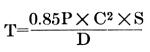
where T=the rated tractive force at rim of driving wheels in
pounds.
P=the boiler pressure in pounds per square inch.
C=diameter of cylinders in inches.
S=stroke in inches.
D=driving wheel diameter in inches.
As the speed is increased the available tractive force falls
off slowly until a point is reached at which the boiler can no
longer supply the steam required by the cylinders at full stroke.
To attain higher speeds the cut-off must be shortened, after which
the available tractive force falls more rapidly. It is evident
that, under these circumstances, the tractive force that a locomotive
can develop is dependent not only on the cylinder and driving
wheel dimensions, but also on the steaming capacity of the boiler.
For practical purposes this may be taken as directly proportional
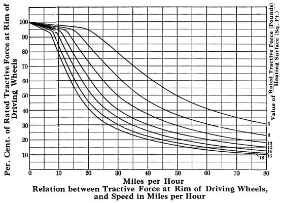
to the total heating surface. Then, as is shown by the curves
in next diagram, the available tractive force at any speed will
depend on the relation between the rated tractive force and the
total heating surface. Each curve corresponds to a different value
of this relation. The vertical scale measures the available tractive
force as a percentage of the rated tractive force, while on the
horizontal scale the speed is measured in miles per hour. The
curves assume that at the high speeds one horse-power can be developed
at the tread of the driving wheels for every two and one-half
square feet of heating surface, and they allow for a lower efficiency
at slow speeds.
In assuming as above that the steaming capacity is directly
proportional to the total heating surface, it is essential that
the ratio of grate area to heating surface be properly suited
to the quality of the fuel. It is also assumed that sufficient
fuel can be fired to enable the steam production to be pushed
to the limit set by the heating surface.
As an example of the use of the curves, suppose it is desired
to find the available tractive force at a speed of forty miles
per hour, for a locomotive having the following dimensions:
Cylinders, 22" x 28"
Driving wheels, 69" diameter
Steam pressure, 200 pounds
Heating surface, 4150 square feet
From the formula on the preceeding page, it is found that the
rated tractive force of this locomotive is 33,400 pounds. The
ratio of rated tractive force to heating surface is therefore
 =8.0. Referring to the curve herewith, it is seen
that the vertical line representing 40 miles per hour intersects
the curve marked 8, on a horizontal line representing 47 per cent.
Hence, the tractive force developed by this locomotive at a speed
of 40 miles per hour, will be =8.0. Referring to the curve herewith, it is seen
that the vertical line representing 40 miles per hour intersects
the curve marked 8, on a horizontal line representing 47 per cent.
Hence, the tractive force developed by this locomotive at a speed
of 40 miles per hour, will be
33,400 x .47=15,700 pounds.
In order that a locomotive may employ all of its rated tractive
force in hauling a train, it is desirable that the weight on driving
wheels be at least 4 times the rated force; or, in other words,
not more than 25 per cent. of the adhesion weight can be utilized
as tractive force.
In the case of locomotives equipped with compound cylinders
or superheaters, the proportion of the rated tractive force developed
at any speed will be from 10 to 20 per cent. higher than that
shown by the curves.
Relation of Rated Tractive Force to Heating
Surface
Average values of the quotient obtained by dividing the rated
tractive force in pounds by the total heating surface in square
feet, for different classes of engines, are given below:
Atlantic (4-4-2) type, 8
Pacific (4-6-2) type, 9
American (4-4-0) type, 10
Mikado (2-8-2) type, 10
Ten-wheeled (4-6-0) type, 11
Consolidation (2-8-0) type, 14
Switching Locomotives, 16
Train Resistance
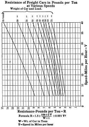
The chart herewith represents the resistance, in pounds per
ton, for freight cars of different weights, at speeds varying
from 5 to 40 miles per hour, on straight level track. These curves
are based on the results of experiments conducted by Prof. Edward
C. Schmidt, on the Illinois Central Railroad. Recent tests show
that the resistance of light cars is greater, in pounds per ton,
than that of heavy cars. Thus, a car weighing 75 tons is seen,
from the table, to have a resistance of 5 pounds per ton at a
speed of 35 miles per hour, while a car weighing only 20 tons
has a resistance of 11.1 pounds per ton at the same speed.
A formula which gives results approximately agreeing with the
curves, is as follows:
This formula is worked out for a speed of 5 miles per hour.
For higher speeds, add 2 per cent. for each mile per hour above
5. The formula should not be used for speeds exceeding 30 miles
per hour.
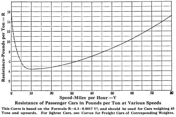
The resistance of passenger cars in pounds per ton on straight,
level track, is represented by the diagram herewith. The curve
here shown is based on the results of recent experiments with
modern rolling stock, and is applicable to cars weighing 45 tons
and upward. For lighter cars use the diagram on page 13, selecting
the line which applies to the particular weight of cars in question.
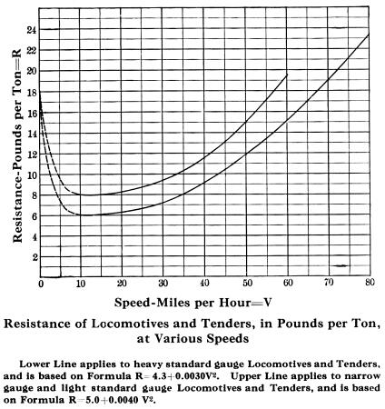
The diagram herewith, represents the resistance of the locomotive
and tender in pounds per ton. Two lines are shown, the lower one
being applicable to heavy standard gauge engines, and the upper
one to narrow gauge and light standard gauge engines. These curves
generally follow that for passenger cars, plus an amount sufficient
to cover the head end resistances.
The resistance due to grades is discussed a little further
on in this text.
Superheating
The temperature to which it is necessary to raise water before
it can be evaporated into steam, depends upon the pressure. For
every given pressure there is, therefore, a corresponding minimum
temperature at which steam can exist. Steam existing at this temperature
is said to be saturated, and any reduction in temperature will
cause some of the steam to be condensed as water. If the temperature
is above that of saturation the steam is said to be superheated.
A device employed for the purpose of raising the temperature of
steam above that of saturation, is called a superheater.
The temperature of the cylinder walls of a locomotive is constantly
changing, owing to the variation in the steam temperature due
to expansion. As a result there is considerable condensation of
steam, causing a loss in efficiency. The object in using superheated
steam is to reduce this loss, by raising the steam temperature
to such a point that condensation is, to a large extent, avoided.
Furthermore since the volume per pound of superheated steam is
greater than that of saturated steam at the same pressure, there
is a gain in efficiency, because each pound of water evaporated
forms a larger volume of steam, and therefore fewer pounds of
steam are required to fill the cylinders.
The type of superheater generally used in locomotive work is
known as the firetube. It is designed to give from 150 to 200
degrees of superheat, and in some cases even higher temperatures
are attained. The superheater pipes are placed in a number of
large tubes, which are about five and one-half inches in diameter.
These tubes, like the small boiler tubes, convey the products
of combustion from the firebox to the smokebox. A double loop
of superheater pipes is usually placed in each large tube, and
the pipes extend from the headers in the smokebox, to within a
short distance of the firebox. The hot gases passing through the
large tubes, both heat the water and superheat the steam. A damper
is usually placed in the smokebox to cut off the draft through
the large tubes when the throttle is closed. This is for the purpose
of preventing the burning out of the superheater pipes when no
steam is passing through them. The nature of the service to be
performed, size and type of locomotive, and various other factors,
must be considered when applying superheaters.
The locomotives described in the tables in this catalogue can
be designed to use superheated steam, provided operating conditions
are favorable. The superheater is of special value in heavy locomotives,
which must develop high horse-power for sustained periods of time.
Piston Speed
The figures at the top of the chart herewith, represent the
diameter of the driving wheels in inches, and those at the left
hand side indicate the piston speed in feet per minute. The several
curves in the body of the chart represent different strokes of
piston.
Follow the perpendicular line from the number representing
the diameter of wheel selected until it intersects the curve representing
the desired stroke; then follow the horizontal line from the point
of intersection to the left hand margin, and the figure here given
will denote the piston speed.
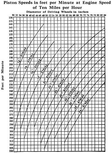
It will be noted that the calculations are based on an engine
speed of ten miles per hour. Greater speed will be determined
by multiplying the results by the proper factor indicated by the
speed required. In locomotive practice the maximum piston speed
should not exceed 1600 feet per minute. The economical speed may
be placed at about 1100 feet per minute.
Horse-Power
The term horse-power was first established by James Watt, who
ascertained that a strong London draught. horse was capable of
doing work for a short interval of time equivalent to lifting
33,000 pounds through a height of one foot in one minute.
This value was used by Watt in expressing the power of his
engines, and has since been universally adopted in mechanics.
The unit of work is the foot-pound, which is the amount of work
required to lift a weight of one pound through a space of one
foot.
Horse-power is the measure: of the rate at which work is performed,
and is equal to 33,000 pounds lifted one foot in one minute, or
one pound lifted 33,000 feet in one minute, or one pound lifted
550 feet in one second; therefore, one horse-power equals 550
foot-pounds per second.
The general formula for ascertaining the horsepower of a locomotive
is as follows:
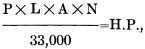
in which
P=mean effective pressure in pounds per square inch.
L=length of stroke in feet.
A=area of the piston in square inches.
N=number of strokes (four times the number of revolutions) per
minute.
H. P.=indicated horse-power.
By cancellation and substituting the diameter of the driving
wheels, the formula may be reduced to the following:
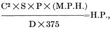
in which
C=diameter of cylinder in inches.
P=mean effective pressure at given speed.
S=length of stroke in inches.
M. P. H.=miles per hour.
D=diameter of driving wheels in inches.
H. P.=horse-power.
The tractive force of a locomotive, multiplied by the speed
in miles per hour, divided by 375, gives horse-power.
Grades
When a train is hauled up a grade, the resistance due to friction
is increased by that due to lifting the train against gravity.
One mile equals 5280 feet; hence a ton of 2000 pounds raised one
foot in one mile, represents a resistance of  or .3788
pounds. Therefore, when the grade is expressed in feet per mile,
the number of feet multiplied by .3788 gives the resistance in
pounds per ton of 2000 pounds. When the grade is expressed in
feet per hundred or per cent., the per cent. of grade multiplied
by twenty gives the resistance in pounds per ton of 2000 pounds. or .3788
pounds. Therefore, when the grade is expressed in feet per mile,
the number of feet multiplied by .3788 gives the resistance in
pounds per ton of 2000 pounds. When the grade is expressed in
feet per hundred or per cent., the per cent. of grade multiplied
by twenty gives the resistance in pounds per ton of 2000 pounds.
The resistance due to friction must, of course, be added to
that due to the grade, in order to find the total resistance of
the train.
The accurate method of determining a grade is by means of surveyor's
instruments, but if these are not available the following method
will suffice, unless the inclination is very moderate. A straight
edge, 100 inches long, with one end resting on the rail, is leveled
by means of a spirit level; and the vertical distance between
the other end of the straight edge and the rail is measured. This
distance expressed in inches, equals the grade in per cent.; and
when the inclination is at all steep the result so obtained is
fairly accurate.
Curves
In the United States it is customary to express curvature in
degrees noted by twice the deflection from the tangent measured
at stations 100 feet apart. In other words, the number of degrees
of central angle subtended by a chord of 100 feet represents the
"degree curve." One degree of curvature is equal to
a radius of 5730 feet. Therefore, the number of degrees divided
into 5730 gives the radius in feet, or, per contra, the number
of feet radius divided into 5730 gives the number of degrees.
This assumes that the 100 feet are measured on the arc instead
of the chord, but the error is so slight on curves commonly used
that it may be ignored for ordinary calculation.
In Great Britain it is common to define a curve as so many
chains (sixty-six feet) radius. Thus the radius of a one degree
curve expressed in chains would be  =86.81; therefore,
86.81 divided by the degrees equals the radius in chains; or 86.81
divided by the radius in chains equals the degrees. =86.81; therefore,
86.81 divided by the degrees equals the radius in chains; or 86.81
divided by the radius in chains equals the degrees.
In the metric system instead of the stations being 100 feet
apart they are taken at twenty metres (65.61 feet). The central
angle remaining the same, the radius must necessarily be less.
This is represented by  for a one degree curve, or
approximately five-eighths, English measurement, which can be
used as a factor for converting the English to the French system. for a one degree curve, or
approximately five-eighths, English measurement, which can be
used as a factor for converting the English to the French system.
The resistance due to curves averages from 0.7 to 1.0 pound
per ton per degree of curvature, depending upon weight of cars,
condition of track, etc.
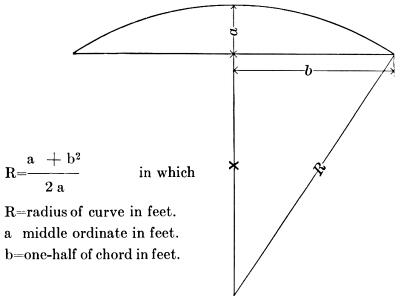
Radius of Curves
To determine the radius of any existing curve, lay off carefully
on the inside rail, by any convenient means, a chord of any desired
length, as shown in the accompanying diagram. Note the center
height or middle ordinate of the chord (a) in feet or fraction
of a foot. The formula is as follows:
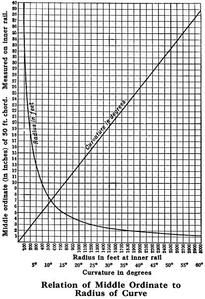
A simple method for approximately measuring the degree of curvature
is as follows: Let the chord equal two rail lengths, then half
the chord, or measurement b, will be approximately thirty feet,
and the height of the middle ordinate a in inches will nearly
equal the curvature in degrees.
The diagram herewith, gives the radius in feet, and the curvature
in degrees, for ordinates from one to forty inches measured on
a chord of fifty feet in length.
Radii of Curves at Switches
The following table, compiled from the Manual of the American
Railway Engineering Association (1915), gives the radii of curvature
at point switches using different frogs. In each case the switch
is supposed to lead from a tangent, and the radius is measured
to the center of the track:
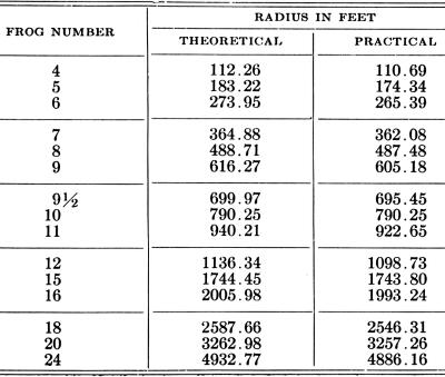
The theoretical radii are mathematically computed. In order,
however, to reduce rail cutting and rail waste, it is usually
desirable to use the "practical" instead of "theoretical"
radius; as the straight lead rail is then of a length to permit
the eventual utilization of both pieces into which a rail is cut.
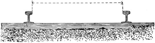
Gauge of Track
The measurement for track gauge is understood to represent
the distance between the inside edges of the heads of the rails,
as shown in the accompanying sketch, and the distance over the
flanges represents the gauge less the required amount of play
or clearance between the flange of the wheel and the rail.
When deciding the gauge for a contemplated road, the following
suggestions will be found useful:
If the line is to connect with any standard gauge road, the
track should correspond and be of the standard broad gauge, which
is four feet eight and one-half inches.
If such connection is unlikely and narrow gauge is considered
preferable, the standard narrow gauge should be adopted, which
is three feet.
The advantage of adopting one of these standard gauges, is
that, should it be desirable at any time to sell the equipment,
a ready market can be found.
For logging railroads the standard gauge of four feet eight
and one-half inches is generally preferable, as the cars can then
have long bolsters and be heavily loaded without piling the logs
too high.
While some roads use the same gauge in curves as on tangents,
it is desirable in order to insure easy riding and reduce wear,
to widen the gauge in the curves. It is stated in "Trautwine's
Engineer's Pocket Book," that the gauge is usually widened
by from one-thirty-second inch to one-eighth inch for each degree
of curvature, the maximum amount seldom exceeding one inch.
Rails
The number of driving wheels required is determined by the
weight which they must necessarily carry and the strength of the
rail or permanent way. As an approximate calculation it may be
assumed that steel rails, properly supported by crossties, can
sustain, as a maximum, a weight per wheel of 225 to 300 pounds
for each pound per yard of rail. It is, therefore, easy to ascertain
the load which any given rail section will support.
Example. With a rail section of forty pounds per yard
the maximum weight for each wheel will be 40 x 300 =12,000 pounds.
This with a locomotive having two pairs of driving wheels will
equal an available weight on driving wheels of 48,000 pounds,
or with three pairs of driving wheels, of 72,000 pounds.
To ascertain the weight of rails per mile of single track to
be laid of any given section, the following formula may be used:
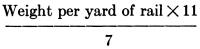 =Tons of 2240 pounds =Tons of 2240 pounds
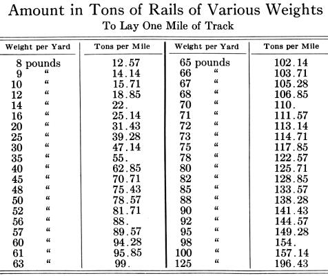
Example. For a road equipped with 40-pound rails the
number of tons required per mile will be:
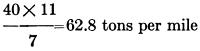
The following table is deduced from the above formula:
Spikes
The following table, giving data referring to railroad spikes,
is taken from the hand book of the Cambria Steel Company, Johnstown,
Penna.
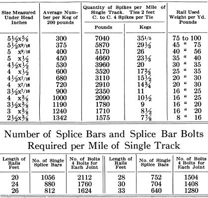
Crossties
A crosstie 9 x 7 inches and 8½ feet in length contains
3.719 cubic feet. If placed two feet apart, from center to center,
it will take 2640 per mile. If placed 2½ feet, 2112; and
if placed 3 feet, 1760 per mile will be required.
Fuel Consumption
Assuming that one-half stroke cut-off represents the average
work of the cylinders for a given run, the water consumption will
be about twenty-five pounds or three gallons per horsepower per
hour, and the consumption of coal about one pound per gallon of
water or three pounds per horse-power.
Wood as Fuel
On logging railroads wood is frequently used as fuel for locomotives.
The following data regarding the heating value and composition
of various woods has been selected from "Kent's Mechanical
Engineer's Pocket Book."
HEATING VALUE of WOOD-The weight of one cord of wood (thoroughly
air dried) is about as follows:
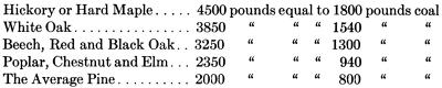
From the above it is safe to assume that two and one-quarter
pounds of average dry wood are equal to one pound of the average
quality of soft coal, and that the fuel value of the same weight
of different woods is very nearly the same—that is a pound
of hickory is worth no more for fuel than a pound of pine, assuming
both to be dry. It is important that the wood be dry, as each
ten per cent. of water or moisture in wood will detract about
twelve per cent. from its value as fuel.
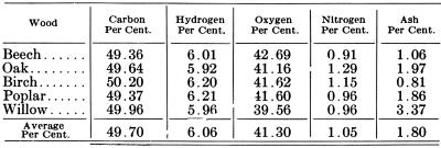
The following table gives the composition of several kinds
of wood:
Smoke Stacks
The Radley and Hunter stack has been extensively used on wood
burning locomotives, and has proved to be a most efficient spark
arrester. This stack is provided with a straight inside pipe,
over which is placed a cast iron cone having volute flanges on
its under side. The outside casing of the stack is balloon shaped.
It has a diameter at the bottom 5 to 8 inches greater than the
inside pipe, with a maximum diameter approximately four times
that of the inside pipe. The sparks are given a rotary motion
when they strike the cone, and are broken up and extinguished.
Such refuse as does not escape to the atmosphere, falls to the
bottom of the outside casing, and is removed through a cleaning
hole. As a further precaution, netting is provided, through which
the products of combustion must pass before escaping from the
stack.
In some instances wood burning locomotives are fitted with
a straight open stack. An extended smokebox, equipped with fine
netting and deflecting plates, should then be used.
Oil Fuel for Locomotives
The development, during the past twenty years, of oil fields
in this country as well as abroad, has greatly increased the available
supply of petroleum for fuel purposes, and has in some districts,
resulted in the extensive introduction of oil burning locomotives.
Petroleum possesses certain advantages which render its use desirable
where it can be obtained at less cost than other forms of fuel.
One pound of oil possesses nearly as much heating power as two
pounds of coal, and probably as much as four pounds of wood, and
the ease with which the fuel may be handled and the fire regulated
to suit conditions of working, results in considerable economy
where an abundant supply is available.
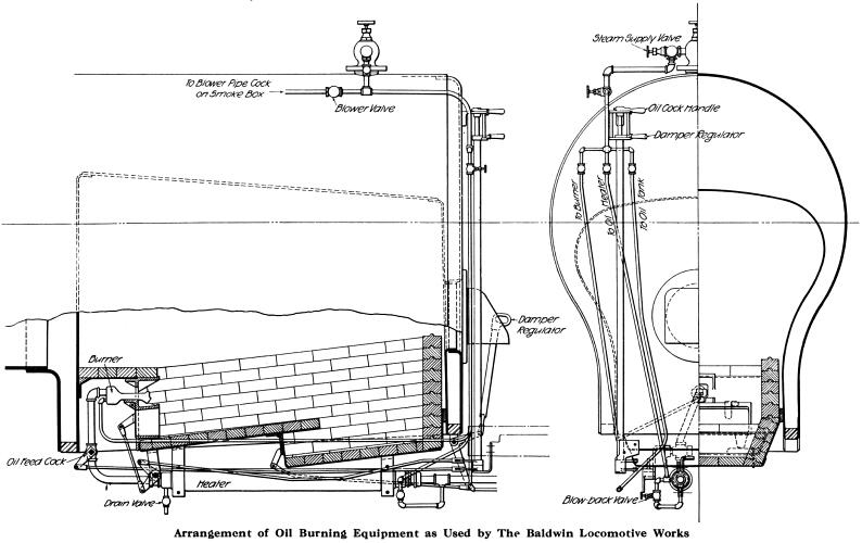
A convenient arrangement of apparatus, which has been extensively
used for burning fuel oil, is shown in the accompanying illustrations.
The burner is located in the front of the firebox, and dampers
for the admission of air are placed beneath it and at mid-length
in the firepan. It is essential to have an arrangement that will
break up and atomize the oil, as without these conditions the
combustion will not be complete, and smoke and loss of economy
will result. The burner is rectangular in cross section with two
separated ports or chambers (one above the other) running its
entire length. Into the upper of these ports the oil is fed through
suitable pipes. Steam is admitted to the lower part of the burner
through a pipe connected to the boiler, and as the oil flows out
it is met by the jet of steam which atomizes it and sprays it
into the fire box. The flow of oil is regulated by a plug cock
in the feed pipe, provided with an operating handle placed within
easy reach of the fireman. The arrangement of the fire bricks
and firepan is clearly shown in the sections through the firebox.
A proper regulation of the quantity of air admitted through the
dampers is of importance, in order to secure perfect combustion,
and the dampers are arranged to close air tight and have substantial
rigging to operate them. The fire door is also air tight and is
provided with a peep hole for observing the condition of the fire.
But little change is necessary in the construction of the tender,
the oil tank being placed in the fuel space. Means are provided
for discharging steam into the oil tank, in order to keep the
fuel sufficiently liquid to flow readily; and an auxiliary heater
is usually placed in the pipe line leading to the burner.

The best adjustment of the diaphragm plates in the smokebox,
and of the regulating plate for the steam jet in the burner, is
found by experiment, and further change of these parts need not
be made except for cleaning or repairs. If the apparatus is in
wood working condition, engines after standing all night with
stack covered, and dampers closed, will have sufficient steam
pressure in the morning to spray the oil jet properly so that
the burner can be lighted.
Qualities of Coal
In designing locomotives for burning a particular quality of
coal, the question is likely to arise as to what is anthracite
or what is bituminous. The division between the different grades
is largely empirical. That given by Kent has been adopted as generally
satisfactory and is as follows:
ANTHRACITE—all coal with less than 7.5 per cent. volatile
matter in combustible.
SEMI-ANTHRACITE—all coal with 7.5 per cent. to 12.5 per
cent. volatile matter in combustible.
SEMI-BITUMINOUS—all coal with 12.5 per cent. to 25 per cent.
volatile matter in combustible.
BITUMINOUS—all coal with 25 per cent. to 50 per cent. volatile
matter in combustible.
LIGNITE—all coal with more than 50 per cent. volatile matter
in combustible.
When coal is of a doubtful quality a sample can be forwarded
for analysis and specifications will be furnished for locomotives
guaranteed to meet requirements and burn the coal to advantage
if practicable.
Logging Service
For logging service the standard gauge of four feet eight and
one-half inches is generally preferable. It is found economical
to use steam power even where the output is comparatively small
and the distance covered is short. It is estimated that under
ordinary conditions the total cost of hauling by steam power including
interest and depreciation is from 30 to 60 cents per 1000 feet
of lumber cut.
Plantation Service
Locomotives used in plantation service are usually narrow gauge.
Sugar cane and other products are handled by steam power in a
large number of plantations in the United States, West Indies,
Mexico, Central and South America, Hawaii and the Philippines.
Industrial Service
For use in steel and blast furnaces and other manufacturing
establishments locomotives have become indispensable. They can
be operated if necessary for twenty-four hours per day without
serious inconvenience, and by their use the work is accomplished
in a more economical manner than by any other form of power. For
shifting cars from main lines to factory yards, where power belonging
to the railroad company is not always available, it is often found
more economical to install locomotives to prevent unavoidable
delays.
Contractors' Service
In moving material for railroad or other excavations, locomotives
can be adapted to run on light, temporary track which is easily
shifted, and thus do the work at a cost far below that which would
be incurred if animal power were used. Besides this, a great saving
of time is made, which in work of this description is generally
of the utmost importance.
Coke Ovens
For feeding coke ovens the steam locomotive furnishes the most
economical and satisfactory power.
Mine Service
It is frequently more convenient with the output of the mine,
either coal or ore, to make delivery in mine cars at the point
of shipment without breaking bulk. To do this locomotives are
required of a gauge corresponding to that of the mine car.
In some instances these locomotives are required to run in,
as well as about, the mine; in which case they must be adapted
for use underground and conform in height and width to the dimensions
of the gallery in which they are to operate.
Cable Codes
The cable address is "Baldwin, Philadelphia." Each
of the following tables has a code word in the line opposite the
class numbers, the use of which indicates that a locomotive of
the class and general dimensions shown on the line referred to
is required. The following codes are used: Lieber's; Al; A-B-C,
fourth and fifth editions; Western Union; Vanguard; Commercial
Code (Atlantic Cable Code), and The Baldwin Locomotive Works Private
Code.
Locomotive Types
Class
Designation
Four Coupled Switching
 Type 0-4-0 Type 0-4-0
Four coupled switching locomotives have all the weight on the
driving wheels, and are suitable for contractors' or industrial
service, and also for light switching work in railroad yards and
terminals. These engines have short wheel bases, and they can
be safely operated on sharp curves and switches. The smaller classes
can easily traverse curves of fifty feet radius. For short runs,
or for switching service where a large fuel and water supply are
not required, saddle or side tanks can be used and the fuel carried
in the cab or on a rear extension of the engine frames. For longer
runs, a separate tender should be employed. If desired, the tender
tank is made with a sloping back, thus giving the enginemen a
better view when backing up. A separate tender is also an advantage
on exceptionally narrow track, as it admits of a lower center
of gravity than if the tank were placed on the boiler.
In the tank-frame locomotives, the frames consist of steel
plates, between which the water tank is placed. This construction
lowers the center of gravity; an important feature where the gauge
is unusually narrow. These engines are fitted with a simple design
of Marshall valve gear, having all its parts outside the wheels
where they are easily accessible. This style of gear has had a
thorough trial on light industrial locomotives operating under
the most severe service conditions.
Four Coupled with Two-Wheeled Front
Truck
Type 2-4-0
Four coupled locomotives, with two-wheeled leading trucks,
are suitable for service where the runs are short and the speed
moderate. Two pairs of wheels are equalized together, either the
driving wheels with each other or the front pair of driving wheels
with the pony truck.
The truck has a swinging bolster and radius bar. Engines of
this type readily traverse curves of short radius. A separate
tender is usually provided, but if the run is short these locomotives
can be designed with either saddle or side tanks.
Four Coupled with Two-Wheeled Rear
Truck
Type 0-4-2
This type is particularly serviceable for operating short lines,
where limited water and fuel capacity will answer. These locomotives
have their driving wheels equalized together, the truck being
center-bearing, with swinging bolster and radius bar. Having a
comparatively long total wheel base and a short rigid wheel base,
they are steady, and ride smoothly without plunging, curve readily,
and cause little wear of track. The fuel is carried on the engine
frames at the back; the water is carried either in saddle or side
tanks, or in a tank back of the cab. The latter plan is better
for light rails. If the tank is placed on the boiler, its weight
adds to the adhesion and increases the hauling capacity, greater
space is afforded the enginemen in the cab, and a larger supply
of fuel may be carried. The weight is well distributed, the principal
portion being carried on equalizing levers between the driving
wheels, thus affording an equal distribution on these wheels.
The pony truck carries the weight of the fuel or the fuel and
water, as the case may be, with a part of the weight of the overhanging
firebox. These locomotives are well adapted for running in either
direction.
American Type
Four Coupled with Four-Wheeled Front Truck
Type 4-4-0
American type locomotives, having four coupled wheels and a
four-wheeled leading truck, are suitable for passenger, freight
and mixed service, where the run is of such length as to require
a separate tender, or for short lines intended ultimately to be
extended. The name "American" type was given for the
reason that for many years locomotives of this type were used
more than any other, for nearly every variety of service throughout
the United States.
Forney Type
Four Coupled with Four-Wheeled Rear Truck
Type 0-4-4
Forney type locomotives, having two pairs of coupled wheels
and a four-wheeled rear truck, are compact and powerful for their
aggregate weight, and are suitable where the run is not long enough
to necessitate a separate tender. The constant weight of the boiler
and machinery is on the driving wheels, while the variable weight
of fuel and water is on the truck. Locomotives of this type are
used as double-enders, being run with equal facility forward or
backward. The driving wheels are equalized together; the truck
is center-bearing and has a swinging bolster. These locomotives
readily traverse curves of short radius. Standard gauge locomotives
of classes 8-161/3-C and 8-181/3-C
have been used on curves of ninety feet radius in passenger service.
The fuel and water are carried at the rear of the cab.
Four Coupled Double-Ender
Types 2-4-2- and 2-4-4

Locomotives having four coupled wheels and a truck at each
end, are suitable for logging, industrial or light road service.
These engines ride steadily on uneven tracks, and can be safely
run in either direction. They are built with saddle, side, or
rear tanks; or, if the runs are long, separate tenders may be
used. As a rule, both the front and rear trucks have two wheels;
but if the tank is placed back of the cab, on an extension of
the engine frames, a four-wheeled rear truck should be used. When
both trucks have two wheels, the front is center bearing and is
equalized with the first pair of driving wheels; while the rear
truck is side-bearing, and is equalized with the second pair of
driving wheels.
The following pages present series of narrow and standard gauge
locomotives with saddle or side tanks, and of standard gauge locomotives
with rear tanks and with separate tenders.
Atlantic Type
Four Coupled with Four-Wheeled Front Truck
and Trailing Wheels
Type 4-4-2
Locomotives of this type are particularly suitable for high-speed
passenger service. The driving wheels are located under the waist
of the boiler, and the front end of the engine is carried on a
four-wheeled truck. A firebox having ample grate area and volume
is placed back of the rear driving axle, and the overhanging weight
is carried by a pair of trailing wheels. This arrangement provides
a boiler having large steaming capacity in proportion to the adhesion-an
essential feature of a high-speed locomotive.
In locomotives of this type the firebox may be placed entirely
back of the driving wheels if desired, thus allowing an increased
width of furnace. The trailing wheels may be placed in a radial
truck, or may be held in rigid pedestals. In either case, these
wheels are equalized with the driving wheels. The leading truck
is provided with a swing bolster, and all the wheels under the
locomotive have flanged tires. The compact grouping of the driving
wheels permits the use of short coupling rods, thus reducing the
liability of breakage when running at high speed.
Six Coupled Switching
 Type 0-6-0 Type 0-6-0
Locomotives of this type are more generally used for switching
service than any other. They are also suitable for heavy contractors'
service, and for industrial work about mills, furnaces and large
manufacturing plants. Tank locomotives of this type are suitable
for short runs, and for switching work where large fuel and water
capacity are not required. Ordinarily, however, a separate tender
is to be preferred; especially with the heavier classes of narrow
gauge engines, where the use of saddle or side tanks may raise
the center of gravity too high. In the case of heavy standard
gauge engines also, it is difficult to secure adequate fuel and
water capacity without using a separate tender.
Mogul Type
Six Coupled with Two-Wheeled Front Truck
Type 2-6-0
The Mogul type, with three pairs of coupled wheels and
a two-wheeled leading truck, is primarily designed for road service,
and is suitable where the eight-wheeled or American type would
not afford sufficient power, or where the requisite weight on
the driving wheels, if carried on only two pairs, would be greater
than the rails could safely bear. The front and rear driving wheels
are always flanged, while the middle pair usually has no flanges.
The pony truck has a swinging bolster and radius bar. The plans
illustrated show:
First.—A locomotive with a deep firebox between the middle
and rear driving axles. This design has the advantage of giving
ample depth of firebox, but necessitates a greater spread of wheels
than is admissible in some instances.
Second.—A locomotive with a firebox placed above the frames
and over the rear axle. This design admits of the driving wheels
being grouped closely together. It answers well where coal is
the fuel, but where wood is burned a deep firebox is desirable.
Third.—A locomotive with the driving wheels grouped closely
together and a firebox placed entirely back of them. The depth
of firebox is sufficient for burning either wood or coal. The
short driving wheel base admits of traversing curves of short
radius. Connection to the tender is made by means of a radial
drawbar passing through the ash pan.
Six Coupled with Two-Wheeled Rear Truck
Type 0-6-2
Six coupled locomotives, with two-wheeled rear trucks, are
suitable where the runs are not long enough to require a separate
tender. The addition of a truck avoids the uneven motion to which
short wheel base locomotives, with a long overhang, are subject.
The increased space back of the cab permits of greater coal
capacity and more room for the enginemen than is practicable without
the truck. The three pairs of driving wheels are equalized together;
the truck is center bearing, and has a swinging bolster and radius
bar.
Ten-Wheeled Type
Six Coupled with Four-Wheeled Front Truck
Type 4-6-0
The ten-wheeled type, having three pairs of coupled wheels
and a four-wheeled front truck, is suitable where a locomotive
of the American type would not afford sufficient power, or where
the requisite weight, if carried on only two pairs of driving
wheels, would be greater than the rails could safely bear. The
greater length of these locomotives admits of a longer boiler,
with increased heating surface as compared with the American type.
The front and rear driving wheels are preferably flanged, and
the truck made with swinging bolster. The main driving wheels
are made with either plain or flanged tires, according to service
requirements.
Three plans of standard gauge locomotives are shown, viz.:
First.—With firebox between the main and rear driving
axles.
Second.—With firebox above the rear driving axle.
Third.—With firebox above the rear pair of driving wheels.
The last arrangement is particularly suitable for heavy engines,
as a large grate area can be provided without using an excessively
long firebox.
Six Coupled Double-Ender
 Type 2-6-2 Type 2-6-2
Six coupled double-ender locomotives, with two-wheeled front
and rear trucks are suitable where it is desired to run forward
or backward without turning, and where the weight required for
adhesion cannot be carried on two pairs of wheels without overloading
the rails.
The front truck is equalized with the front pair of driving
wheels, and the rear truck with the middle and rear pairs of driving
wheels. The front truck is center-bearing, the rear truck is side-bearing.
Each truck has a swinging bolster and radius bar. This arrangement
enables the engine to ride smoothly, and each wheel finds a bearing
on the most uneven track. The middle pair of driving wheels has
plain tires. A saddle tank covering the boiler or two rectangular
tanks, as illustrated, can be used.
For longer runs a separate tender is provided. A large number
of engines of this type have been built for logging roads, and
in such service they are giving most satisfactory results.
Pacific Type
Six Coupled with Four-Wheeled Front and
Two-Wheeled Rear Trucks
Type 4-6-2
The Pacific type is a high-powered design, having three pairs
of driving wheels grouped under the waist of the boiler, a four-wheeled
front truck, and a two-wheeled rear truck.
The firebox is placed back of the rear driving wheels, and
the overhanging weight is supported by the rear truck. The result
is a locomotive having ample adhesion weight and tractive force,
together with a boiler of high steaming capacity, thus enabling
the engine to haul heavy loads at sustained speeds.
The rear trucks can be designed with either inside or outside
journals. They are equipped with radius bars, and are equalized
with the driving wheels; by which means a flexible wheel base
is obtained.
Pacific type locomotives are specially suitable for heavy,
fast passenger service, and are also proving successful in fast
freight service.
Eight Coupled Switching
Type 0-8-0
This type of locomotive is suitable for heavy switching service,
where the weight necessary for adhesion is too great to be safely
carried on three pairs of wheels. Such requirements are found
in hump yards, where locomotives of high tractive force are needed
to push trains over the hump; also in heavy terminal and transfer
service, and to a lesser extent in industrial work, or for general
switching purposes where the engines must operate on light tracks.
Separate tenders are preferably used with locomotives of this
type.
Consolidation Type
Eight Coupled with Two-Wheeled Front Truck
Type 2-8-0
The Consolidation type has four pairs of driving wheels and
a two-wheeled front truck, and is specially suitable for heavy
freight service. A large percentage of the total weight of the
locomotive is available for adhesion; and as this weight is distributed
over four pairs of driving wheels, a high tractive force can be
developed without using excessive wheel loads. The front and rear
pairs of driving wheels are flanged, while the intermediate pairs
have either plain or flanged tires according to service requirements.
The truck has a swinging bolster and radius bar.
Ordinarily in this type a long firebox is placed over the rear
driving axle, and is especially adapted for burning coal. In some
instances such engines have been satisfactorily used for burning
wood. A plan for narrow gauge locomotives is also presented in
which a deep firebox overhangs the rear driving wheels. The driving
wheel base is shorter than in engines of the first mentioned type,
because the wheels are placed as close together as possible under
the waist of the boiler. In this design there is ample depth between
the tubes and the grate for the combustion of wood, while the
same plan answers equally well for bituminous coal.
The heaviest classes of standard gauge engines are preferably
built with the grate placed above the rear pair of driving wheels.
This plan provides sufficient grate area, without using a furnace
of excessive length. The tables include a series of engines so
arranged.
Mikado Type
Eight Coupled with Two-Wheeled Front and
Rear Trucks
Type 2-8-2
This type of locomotive is a development of the Consolidation.
The two-wheeled rear truck permits the use of a wide and deep
firebox, which is placed back of the driving wheels. This increases
the steaming capacity in proportion to the adhesion, making these
engines specially suitable for heavy freight service, where long,
hard runs must be made. Owing to the liberal space available for
the firebox, these locomotives can readily be designed to use
inferior grades of fuel; and on several roads they are burning
lignite successfully and economically.
Mikado type locomotives, having a truck at each end, are able
to back into sharp curves and switches without danger of derailment;
and for this reason are proving highly successful in heavy service
on logging and industrial railways. This class of work frequently
requires heavy hauling in addition to switching; and the combination
of excellent steaming and tracking qualities, as found in the
Mikado type, makes it particularly suitable for such service.
Mountain Type
Eight Coupled with Four-Wheeled Front and
Two-Wheeled Rear Trucks
Type 4-8-2
This type is especially suitable for heavy express passenger
service on steep grades, where the necessary tractive force cannot
be developed by a six coupled locomotive. The four-wheeled front
truck provides excellent guiding qualities, and the driving-wheels
can be made of sufficient diameter for fast running. The boiler
is of large diameter, and has a deep, wide firebox, with ample
grate area and furnace volume. This provides high steaming capacity
in proportion to adhesion; an essential feature in heavy passenger
service.
These locomotives are also suitable for fast freight service
on divisions having comparatively light grades, where heavy trains
must be moved at fairly high speeds.
Santa Fe Type
Ten Coupled with Two-Wheeled Front and
Rear Trucks
Type 2-10-2
Ten coupled locomotives are suitable for heavy freight service,
where the weight necessary for adhesion cannot be carried on four
pairs of driving wheels without overloading the rails. The Santa
Fe type is a development of the Mikado, and, like it, has a two-wheeled
rear truck, allowing room for a wide and deep firebox placed back
of the driving wheels. Locomotives of this type have high steaming
and hauling capacity, and have been built to traverse curves of
sixteen degrees, or even, in some cases, of shorter radius. The
tires on the middle pair of driving wheels are usually made without
flanges. The Santa Fe is the largest type of locomotive thus far
produced, in which all the driving wheels are coupled in one group.
Mallet Articulated Locomotives
The Mallet articulated type employs compound cylinders and
two groups of driving wheels. The rear group is driven by the
high pressure cylinders and the forward group by the low pressure.
The rear frames are held in rigid alinement with the boiler, while
the front frames can swing about a hinge pin located on the center
line of the engine between the high-pressure cylinders. The forward
group of wheels thus constitutes a truck, giving sufficient flexibility
to the wheel-base to enable the locomotive to easily traverse
sharp curves. The receiver pipe between the high and low pressure
cylinders, and the exhaust pipe from the low-pressure cylinders
to the smoke-box, are necessarily provided with flexible joints.
These pipes carry low pressure steam only, hence the joints can
be kept tight without difficulty.
Superheaters have been applied to a large number of Mallet
locomotives, with most satisfactory results. The heater is placed
between the throttle and the high pressure cylinders, and sufficient
superheat is obtained to avoid difficulties due to condensation
in the low pressure cylinders.
Mallet locomotives are specially suitable for pushing service,
and for road service where grades are steep, speeds moderate,
and operating conditions unusually severe. They are also fitted
for switching service in hump yards, where heavy trains must,
be pushed up one side of the hump before being classified.
Modifications of the wheel arrangements can, if necessary,
be made to suit special conditions.
Triple Articulated Compound Locomotives
This type is a development of the Mallet. It has three groups
of driving wheels, two placed under the boiler and the third under
the tender. The cylinders of the middle group of wheels are the
high-pressure, and these exhaust simultaneously into the front
and back cylinders. All the cylinders are of the same size, and
are cast from the same pattern; hence the ratio of compounding
is as one to two. The exhaust from the front cylinders is utilized
to create a draft for the fire, while that from the rear cylinders,
after passing through a feed-water heater, is discharged up a
pipe at the rear of the tank. The boiler is held in alinement
with the frames of the middle group of wheels, and the front and
rear frames are hinged to the middle frames. With this construction
these locomotives traverse curves without difficulty. Front and
rear trucks have been applied to all the triple locomotives thus
far built.
These engines, with a large percentage of total weight on driving
wheels, are especially suitable for heavy pushing service where
high tractive force must be developed at comparatively slow speeds.
Fireless Locomotives
These locomotives are specially suitable for switching service
where fire risks must be absolutely eliminated. In place of a
boiler, this type is fitted with a cylindrical tank which is charged
with steam and hot water from a stationary plant. The storage
pressure usually approximates the working pressure of a locomotive
boiler; but the pressure of the steam is considerably reduced
before it enters the cylinders. As the steam is drawn from the
storage tank, the pressure in the latter becomes reduced. When
this occurs, however, a portion of the stored water evaporates,
and the steam supply can thus be maintained until the storage
pressure drops to the cylinder working pressure. The locomotive
should then be recharged. The cylinder proportions are such, however,
that the locomotive can move itself on very much less than the
normal working pressure.
In charging, steam is admitted at the bottom of the reservoir
through a perforated pipe, so that the temperature of the entire
body of water is gradually raised.
These locomotives are simple in construction and, as they cannot
explode, they are exceedingly safe to handle. As a rule, but little
equipment must be installed for their operation, as the majority
of industrial plants are supplied with the boiler capacity necessary
for charging the locomotives.
Contents Page
|