THE LARGEST ARCH BRIDGE IN THE WORLD
Scientific American—June 8, 1907
 An important feature in the costly
improvements being carried out by the Pennsylvania Railroad in
and around New York is the building of a connecting railway for
uniting the systems of the Pennsylvania Railroad and the New York,
New Haven and Hartford Road. This connection will be made by means
of a crossing of the East River, the most important feature of
which will be an arch bridge (the largest in the world) of about
1,000 feet span. The plans for this bridge have been recently
submitted to the Municipal Art Commission for its approval, in
accordance with the franchise granted by this city to the company.
The great steel arch will form part of a steel viaduct, itself
the largest of its type in the world, the whole length of the
structure, from abutment on Long Island to abutment in the Bronx,
being 17,000 feet, considerably over three miles. With a wide,
sweeping curve, the viaduct will pass over Hell Gate, Ward's Island,
Little Hell Gate, Randall's Island and Bronx Kills. It will be
not only the longest, but considerably the heaviest steel bridge
in existence, over 80,000 tons of steel being needed for its construction.
With its completion, the city of New York will find itself in
possession of an all-rail route between New England and the South
and West. Through trains from Boston may then run to New York,
Philadelphia, Baltimore, and Washington, Palm Beach, New Orleans,
Chicago, St. Louis, or any other southern or western city without
leaving the rails. Hitherto cars for such through trains have
been ferried around Manhattan Island from the Bronx to Jersey
City. An important feature in the costly
improvements being carried out by the Pennsylvania Railroad in
and around New York is the building of a connecting railway for
uniting the systems of the Pennsylvania Railroad and the New York,
New Haven and Hartford Road. This connection will be made by means
of a crossing of the East River, the most important feature of
which will be an arch bridge (the largest in the world) of about
1,000 feet span. The plans for this bridge have been recently
submitted to the Municipal Art Commission for its approval, in
accordance with the franchise granted by this city to the company.
The great steel arch will form part of a steel viaduct, itself
the largest of its type in the world, the whole length of the
structure, from abutment on Long Island to abutment in the Bronx,
being 17,000 feet, considerably over three miles. With a wide,
sweeping curve, the viaduct will pass over Hell Gate, Ward's Island,
Little Hell Gate, Randall's Island and Bronx Kills. It will be
not only the longest, but considerably the heaviest steel bridge
in existence, over 80,000 tons of steel being needed for its construction.
With its completion, the city of New York will find itself in
possession of an all-rail route between New England and the South
and West. Through trains from Boston may then run to New York,
Philadelphia, Baltimore, and Washington, Palm Beach, New Orleans,
Chicago, St. Louis, or any other southern or western city without
leaving the rails. Hitherto cars for such through trains have
been ferried around Manhattan Island from the Bronx to Jersey
City.
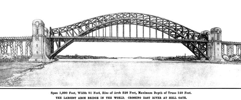
The steel arch which will span the waters of Hell Gate will
have a clear span between abutments of 1,000 feet, made up of
twenty-three panels of about 42½ feet between centers.
The depth of the truss at the ends will be 140 feet; at the center,
40 feet; and at the quarters 66 feet. The reverse curve of the
upper member of the arch at either end is explained by the necessity
of raising the top member of the portal to a sufficient height
above the tracks to allow head room for the trains. At the quarters,
the height has been purposely made such that no increase in the
sections of the arch members is required to meet the bending strains
due to one-sided loading. To this end the height, here, has been
made greater than one-quarter the rise of the arch, which latter
is 220 feet. From this it will be understood that the reverse
curve of the top member of the arch is strictly the result of
the contingencies of the design. The lower arch member has a section
of 9 feet by 6 feet at the bearing and 5 feet by 5 feet at the
center, the width decreasing evenly from the bearing to the crown.
The struts are all riveted box sections, and the suspenders consist
of eight heavy angles laced together.
The floor system is built on the customary method of heavy
cross girders and longitudinal stringers. The floor beams are
8 feet in depth by 80 feet in length. The main arches are placed
in vertical planes 60 feet apart, and the longitudinal portion
of the floor system consists of eight lines of stringers, or two
beneath each of the four lines of railroad track. Above the stringers
is laid a solid wood floor of creosoted 8 x 8-inch timbers, packed
tightly together, and calked. Upon this is 14 inches of stone
ballast, in which are imbedded the cross-ties of the regular Pennsylvania
Railroad standard track system. It should be mentioned here that
the floor beams are the heaviest ever built for a bridge, the
section of the bottom flange of the girders at the center being
6¼ by 24 inches, or 150 square inches.
Wind bracing is carried in the plane of the upper and lower
arches from bearing to crown; but the main wind bracing is carried
in the plane of the roadway, and it is arranged as a cantilever
truss system. The contra-point and expansion joint of the cantilever
are located six panels from each end of the arch; so that the
temperature strains of the suspended floor system will in no way
affect the arches—in other words, the temperature stresses
of the arch and the floor have been made independent of each other.
The maximum compression in the arch is found at the bearing, where
it amounts to 16,800 tons, decreasing from that to 13,600 tons
at the crown. This compression is that due to the combined dead
and live load, wind pressure, and temperature stresses.
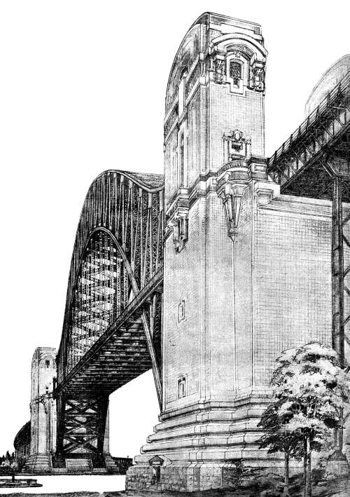
The abutments of the arch will be monumental stone and concrete
towers, which will serve to divide the arch bridge proper from
the steel viaduct which forms the approaches to it. The base of
the tower will be built of granite; and it will rest on foundations
of a very hard gravel at a depth of 20 feet below the surface.
The upper portion of the towers will be built of molded concrete,
and, as will be seen from our illustrations, the design of these
towers is simple, massive, and dignified, and altogether harmonious
with the design of the great arch itself.
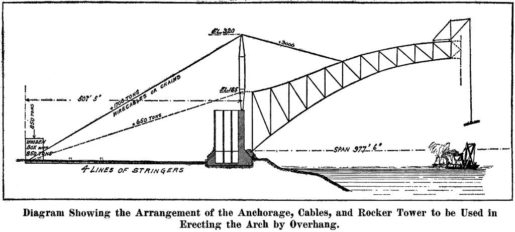
An interesting feature of this bridge is the method of erection,
which will be carried through without the assistance of any false
work in the whole 1,000 feet of its length. The arch will be built
out in two halves simultaneously from each abutment, the steel
work being guyed back to an original system of anchorage constructed
in the following manner: At a distance of 507½ feet inshore
from the abutment two huge wooden boxes or caissons, 12 feet wide,
42½ feet long, and 50 foot high, will be erected on the
surface of the ground and each loaded with 850 tons of pig iron.
Four lines of the stringers, which will subsequently be built
into the floor of the bridge, will be laid in the planes of the
arches in a straight line from each box td the abutment. Upon
the top of the abutment will be erected two temporary rocker posts,
and over these will pass the wire cables or eyebar chains, as
the case may be, which will be used during erection to carry the
load of the arches until they meet at the center of the span.
The four lines of stringers will act as compression members, and
prevent the movement of the deadweight anchorages under the pull
of the erection cable, which latter will reach a maximum figure,
when the arches are well out to the center of the span, of 3,000
tons for each arch. The overhanging arches will be held against
wind pressure during erection by means of two cables carried down
to anchorages, on each side of the main abutment.
After the closure of the arch, the suspenders will be attached
at their upper ends to the panel points of the arches, and to
their lower ends will be riveted the floor beams. Upon the floor
beams will be built in the whole floor system, with its stringers,
wind bracing, wooden floor, etc.
The bridge has been designed to carry on each of its four tracks
a load equivalent to two locomotives, each with a concentrated
load of 52,000 pounds on each of the four drivers, the total weight
of each of the two engines being 190 tons, followed by a train
load of 5,000 pounds to the lineal foot. This would be equivalent
to loading the whole of the four tracks from end to end of the
arch with trains made up of heavy freight locomotives; and so
stiff is the arch that under this load, the deflection at the
center would be only three inches.
The three-mile viaduct will be made up of spans of from 70
to 100 feet, carried mainly on four-column rocker steel bents;
but at every 800 feet of the viaduct there will be a massive stability
pier of concrete, and also an expansion joint. It is estimated
that the bridge can be built in two and one-half years, and at
a probable cost of $12,000,000.
This handsome structure was designed by Mr. Gustav Lindenthal,
the former Bridge Commissioner of this city, to whom we are indebted
for assistance in the preparation of the present article.
Bridge Page
| Contents Page
|