|
Engineering News and American Railway Journal
— July 13, 1889
The Judson Pneumatic Railway System
With the multitude of patents already in existence for propelling
street-cars, it would be but natural to suppose that future inventors
had little left them other than some further improvement upon
methods in use. But in the street railway system about to be described
the direct motive power is independent of horses, steam, electricity,
compressed-air motors on the car or cables. It is, in fact, a
new departure, differing most essentially from all previous schemes
for producing similar results.
As will be better understood by examining the accompanying
illustrations, the Judson system is founded upon a new mechanical
movement, a new method of converting rotary into rectilinear motion.
It is a screw, but without a thread; and this screw
though always revolving in one direction, will send the cars in
either direction, and do this by a pure and simple rolling and
not a sliding friction. But to understand this novel and at first
puzzling mechanical movement, it is best to refer at once to the
cuts shown.
In Figs. 1 and 3 we have illustrated the controlling principle
of this invention. Instead of a cable a line of coupled steel
tubing (A), about 12 ins. in diameter, is run in a subway and
supported at intervals by pillow-blocks. At long intervals this
line of tubing is revolved at a constant speed by any power desirable,
whether water, steam, or electricity; though the introducers of
this system give several good reasons for preferring compressed
air above other motive powers. Successful practice in England
and France has demonstrated the fact that compressed air is one
of the best and most economical methods of transmitting power
from a central station to other stations for use at varying distances,
and its application is less liable than that of other powers to
introduce any element of danger or create a nuisance of any description
on the line of our public highways.
 Coming back to the tube itself,
in Fig. 1 A represents a hollow cylinder with a perfectly
smooth surface rotating on its axis continuously in one direction
E E are friction wheels resting on opposite quarters of
the drum A and adjustable in the planes of their axes,
and like the drum having a perfectly smooth periphery. When in
contact with the moving drum amid in the position No. 1, these
wheels simply rotate without imparting any linear impulse. But
turn them slightly into the position shown in No. 2, and they
move forward on the path of a finely threaded screw, as shown
by the dotted lines, with adhesion between the surfaces taking
the place of the regular screw and nut. In No. 2 position, the
speed is slow, but tractive power is great, just the quality of
power best adapted to starting a car from a state of rest. When
the start is made, more speed is wanted, and the tractive power
can be safely reduced by gradually assuming the positions 3 and
4 in Fig. 1. This change in the position of the motor-wheels is
smooth and gradual and the application and economy of power is
self-evident to every mechanical engineer. Coming back to the tube itself,
in Fig. 1 A represents a hollow cylinder with a perfectly
smooth surface rotating on its axis continuously in one direction
E E are friction wheels resting on opposite quarters of
the drum A and adjustable in the planes of their axes,
and like the drum having a perfectly smooth periphery. When in
contact with the moving drum amid in the position No. 1, these
wheels simply rotate without imparting any linear impulse. But
turn them slightly into the position shown in No. 2, and they
move forward on the path of a finely threaded screw, as shown
by the dotted lines, with adhesion between the surfaces taking
the place of the regular screw and nut. In No. 2 position, the
speed is slow, but tractive power is great, just the quality of
power best adapted to starting a car from a state of rest. When
the start is made, more speed is wanted, and the tractive power
can be safely reduced by gradually assuming the positions 3 and
4 in Fig. 1. This change in the position of the motor-wheels is
smooth and gradual and the application and economy of power is
self-evident to every mechanical engineer.
The reverse of these movements, from No. 4 to No. 1, brings
the car gradually to a stand still again; or if the movement of
the friction wheels is continued until No. 2 stands in the direction
opposite to that shown in the cut, the motion of the car will
be reversed, and it will back with the same speed and power it
had in moving forward, and accomplish this with the drum A
still rotating in its former direction. Thus, with one simple
lever connected with these friction wheels, the operator can start,
stop reverse and vary at will the speed of the car.
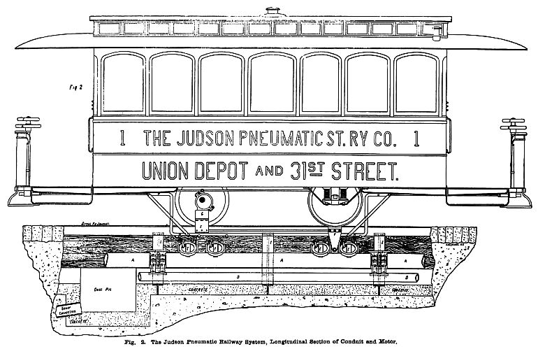
Fig. 2 shows a longitudinal section of the car-propelling mechanism
and the conduit. As it stands, the plane of the friction wheels
is at right angles to the axis of the drum, and the car is stopped.
On the front platform are two hand-wheels, superimposed. The wheel
J is rigidly fastened to a rod terminating in a cog-pinion
under the car platform, and this pinion is in mesh with two racks,
one on either side, which are rigidly connected with the lever
H. This last lever passes down into the conduit, and is
linked by ball-and-socket connections with the spiders which support
the friction wheels E E. By this connection, when the operator
slightly turns the hand-wheel J, all of the friction wheels
on one side of the drum are thrown to a certain angle and all
the wheels on the other side are thrown to exactly the same pitch
line in the opposite direction, and the car moves foward as previously
described.
The hand-wheel K, shown under J in Fig. 2, is
used as follows: As the minimum of pressure between the friction
wheels and the drum A is desirable, this pressure is normally
supposed to be just sufficient to maintain the desired speed on
a level track. A grade or a curve will of course present a greater
resistance and demand an increase in the tractive power to overcome
it. This increase is gained by taking hold of the wheel K,
which is fixed to a hollow shaft surrounding the stem of J,
and by a slight turn operating eccentrics which throw as much
of the weight of the car upon the friction wheels as is desired
to gain the required tractive force. By turning K in the
other direction, the friction wheels can be lifted entirely out
of contact with the drum A, and thus reduce the wear and
tear when standing still. Similar sets of wheels at both ends
of the car avoid any necessity for turning the car at the end
of the route. The wheels E E, in position No. 1, Fig. 1,
constitute in themselves a powerful brake.
In Fig. 2 A is the propelling drum; B is the
pillow-block in which the journals of A rest, completely
housed over to protect it from dust and dirt C is a "bridge
rail" to carry the friction wheels over the space left at
the journals; D is the tube conveying compressed-air; F
is the "slot-blade," or the connection between the traction
wheels and the car; G are "spring-boxes" contain-lug
coiled springs and connected with the axle of the car through
the eccentrics, with the purpose of relieving the friction wheels
from any sudden jar or pounding arising from unevenness of track,
etc.; and I is the cast-iron yoke, similar to those used
in cable construction, but lighter.
The depth from street surface to base of the concrete foundation
to the conduit is 3 ft., and the conduit proper is 2 ft. deep
by 22 ins. wide at the widest point. The bottom of the conduit
is smooth and shaped to form a gutter on each side of the drum.
A brush or scraper could easily be attached to the framework of
the friction wheels and so used as to gather up all dirt and deposit
it in pits (as shown in Fig. 2). The top of this conduit is also
removable (see Fig. 3), and can be lifted out in ten 12 ft. sections
so that repairs may be made without tearing up the street surface.
The small compressed-air engine to be used in rotating the
drum is shown in Fig. 4. In this illustration, M is a small
air pipe conducting the air from the main supply pipe D
into the heater L, where the compressed air is heated to
any desired degree before it is permitted to go into the engine
cylinders through the governor. N is a lever connected
with a clutch, and by it the engines are thrown into or out of
gear with the drum. It wall be observed that one set of these
cylinders drives the drum on both the going and the coming track,
so that one main supply pipe and one set of connections only is
required for each engine. These engines will be placed as shown,
beneath and between the two tracks, in a pit provided for them
and it is believed that they will be required not oftener than
once in 1,500 ft. on straight lines, and perhaps somewhat nearer
if many curves are encountered. They are very simple and inexpensive,
costing not more than $200 each.

In this connection we may say that every detail in regard to
curves, grades, switches or turnouts, crossings, etc., has been
worked out by the inventor until this system stands forth with
such completeness as to be at once a marvel to outsiders and a
tribute to the genius of the inventor. The system is peculiarly
adapted to elevated railroads and would relieve the structure
greatly and abate all nuisances. As the cars can be run in either
direction at the will of the operator, and switches or turn-outs
are easily provided, it is also applicable to single-track lines
in small or suburban cities where traffic will not warrant double
tracks. The offices of the Judson Pneumatic Street Railway Co.
are in rooms 143, 144, 145, Aldrich Court, 45 Broadway, New York
City, where further information concerning this new departure
can be obtained.
Stories Page
| Contents Page
|