THE MEIGS ELEVATED RAILWAY.
Scientific American—July 10, 1886
The roadbed and rolling stock of the railroad of today have
reached their high standard through the labors of countless ingenious
and persevering inventors, each of whom has added his link to
make the chain more perfect; even the smallest detail shows the
combined talent of many industrious workers, one taking it up,
advancing it a step, and then giving place to another. It therefore
seems peculiar to be called upon to describe a new method of railroading
designed as a whole by one man—a new railroad from the ballast
to the top of the smokestack, from the pilot to the coupler on
the last car.
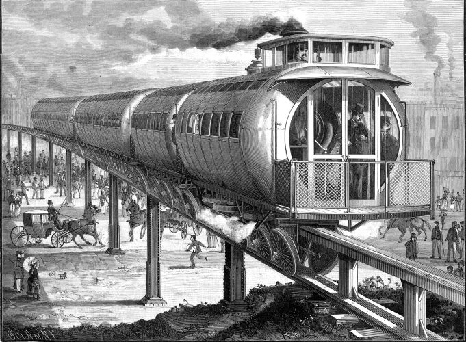
The system herewith illustrated is the invention of Mr. Joe
V. Meigs, of Lowell, Mass., and has been tested under conditions
far more exacting than would be found in actual practice. The
road is not a model, but a full-sized elevated railroad in every
respect. This was made necessary .by a section in the act of the
Massachusetts Legislature authorizing the incorporation of the
Meigs Elevated Railway Company, which states that "no location
for tracks shall be petitioned for in the city of Boston until
at least one mile of the road has been built and operated, nor
until the safety and strength of the structure and the rolling
stock and motive power shall have been examined and approved by
the board of railroad commissioners or by a competent engineer
to be appointed by them." To fully demonstrate the possibilities
of the road under widely varying circumstances, the company has
built tracks of several kinds—wooden way of the cheapest
possible kind; wooden way following the contour of the earth;
wooden way with level grade secured by varying the heights of
the posts; wooden way with very short curves and steep grades;
and iron way upon high grades, increasing in height until a level
of 14 feet in the clear above the earth was secured. The trial
road, beginning at the shops of the company on Bridge St., East
Cambridge, has one curve of 50 feet radius, 165 feet long, on
a grade of 120 feet, and on level and curves has grades of 240
feet, 300 feet, and 345 feet. So far everything has worked in
the most satisfactory manner, the train rounding the exceedingly
sharp curves easily, and mounting the steep grades without trouble.
The peculiar features of this road, wherein it differs roost
essentially front the ordinary railroad, are the way, switch,
trucks, passenger cars, engine, drawbar, and brakes.
The posts for an iron way are made up of two channel bars united
by two plates, thereby forming a box-like structure whose cross
section may be varied as demanded by location. The posts are to
be placed upon foundations, the plans of which vary to suit the
character of the material that may be encountered.
The way upon which the train runs consists of a single iron
girder 4 feet in depth for each span, placed over the center line
of the posts. The girder carries an upper track beam and a lower
track beam, upon the sides of each of which the rails, four in
number, are placed. The two bearing rails, which carry the load
of the train, consist of angle irons placed upon the outer upper
edge of wooden stringers upon the lower track beam. These stringers
are placed in the exterior recesses formed by two channel bars
properly secured to the sides of the posts. These rails are fastened
to each other, to the stringers, and to the track beam by bolts
passing clear through. Two vertically placed rails for the balancing
or friction wheels are carried by the upper track beam. The distance
from out to out between the lower rails is 22½ inches,
this being sufficient to insure the necessary transverse stiffness.
This is the gauge of the road. The distance between the upper
rails is 17½ inches. It is expected to adopt the common
form of rail, beveling the edges of the lower stringers and placing
the rail at an angle of about 45 degrees. In our engraving, the
rails are in the form of a right angle, and the treads of the
wheels are made with a corresponding right angle groove. The usual
length of post, 24 feet, would give a clear headway of 14 feet,
4 feet being taken up by the truss and 6 feet forming the foundation.
The switch is formed of a single swinging section turning upon
a hinge of great strength attached to one of the posts. A movement
of four or five feet by the free end of the switch is enough to
permit the cars and trucks on one track to clear the end of the
other track. The free end travels upon a carriage provided with
rollers moving upon a supporting rail. Suitable mechanism is provided
for operating the switch and locking it in place.
The truck is a development of the conditions controlling the
adoption of the permanent way. It consists of a horizontal rectangular
wrought iron frame, stiffened by cast iron pieces and provided
with stiff pedestals bolted to its under side, in which is a fixed
short axle for the wheels. Each truck has four wheels set at an
angle of about 45 degrees, the axles being properly inclined.
Between the supporting wheels are two horizontal wheels, one on
each side of the upper girder, upon vertical axles attached to
the frame; these wheel bear upon the rails of the upper truck
beam, and are kept in yielding contact with the rails by springs
outside the boxes, and serve as balancing wheels to take the side
oscillations of the cars. They are formed with flanges that pass
under the lower edges of the rails, thus tying the truck to the
rails, so that no lifting or jumping can take place, and there
is no possibility of the trucks running off the track. The wheels
are 42 inches in diameter, have a tread of 3½ inches, and
rotate independently of each other. In case any or all of the
wheels should break, provision is made to prevent the cars from
overturning or leaving the track, by means of a strong shoe, which
would slide upon but could not leave the way. On top of the truck
frame is a movable iron frame carrying four posts containing heavy
spiral springs. These posts interlock with similar spring sockets
bolted to the framing of the floor of the car, which is directly
above the truck and within 18 inches of the top of the girder.
The truck is guided in turning by a center pin, and is securely
tied to the car body, as the horizontal flanges of its frame castings
overlap the rim of the upper turntable. In passing curves and
switches, the trucks turn upon the balancing wheels, placed centrally
between the supporting wheels, which are 4 feet apart.
It has been found that, by reason of the independent motion
of all the truck wheels, curves are followed so closely that practically
the increase of friction of the cars upon curves even as small
as 50 feet radius is too slight to be noticed or measured by weighing
in a model one-eighth full size. This construction of the trucks
also admits of a car 50 feet long turning from a street only 28
feet wide into another of the same width.
 The cars possess
many novel features, both outside and inside. The circular section
and rounded ends admit of the strongest possible construction
without an overweight of material. The floor consists of a platform
made of 5 inch channel beams, and is 7½ feet wide by 51
feet 2 inches long. The framing of the body is of light T iron ribs, bent in a circle, filled
in by panels covered with rich upholstering, which covers all
the interior; the exterior is sheathed with paper and copper.
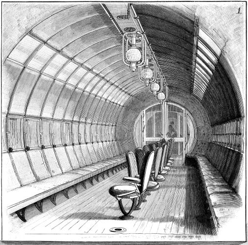
The cylindrical portion is 10 feet 8½ inches in diameter.
While adding to the strength, this form is expected to diminish
the wind resistance fully one-third. The interior of the car,
as shown in Fig. 1, is light, roomy, and pleasing to the
eye. The seats are upholstered like the rest of the car, and comfort
and luxury have been carefully studied in every detail. At each
window is a specially designed device for securing ventilation
without the annoyance caused by dust. There is an entire absence
of sharp corners, so that, in case of a serious accident, the
liability of the passenger being greatly injured is largely avoided. The cars possess
many novel features, both outside and inside. The circular section
and rounded ends admit of the strongest possible construction
without an overweight of material. The floor consists of a platform
made of 5 inch channel beams, and is 7½ feet wide by 51
feet 2 inches long. The framing of the body is of light T iron ribs, bent in a circle, filled
in by panels covered with rich upholstering, which covers all
the interior; the exterior is sheathed with paper and copper.
The cylindrical portion is 10 feet 8½ inches in diameter.
While adding to the strength, this form is expected to diminish
the wind resistance fully one-third. The interior of the car,
as shown in Fig. 1, is light, roomy, and pleasing to the
eye. The seats are upholstered like the rest of the car, and comfort
and luxury have been carefully studied in every detail. At each
window is a specially designed device for securing ventilation
without the annoyance caused by dust. There is an entire absence
of sharp corners, so that, in case of a serious accident, the
liability of the passenger being greatly injured is largely avoided.
The locomotive consists of a platform car supported upon a
truck at either end and housed like the passenger car. The floor
is 7½ ft. wide by 29¼ ft. in extreme length; the
tender is 24-and-two-thirds ft. long, has a tank and bin for the
water and coal, besides additional room which maybe used for other
purposes. Upon the floor of the engine are, in effect, two complete
stationary engines, each connected with a single driving wheel.
The boiler is of the locomotive type, is 60 in. in diameter, 15
ft. in length, and is placed over the engines, its center line
being 61 inches above the floor. There are 200 tubes, 2 in. in
diameter and 7 ft. long; the grate is 4½ ft. square. The
crown sheet is arched in shape, and is inclined downward at the
back end to allow of climbing and descending grades equal to 800
feet to the mile without exposing any uncovered part to the fire.
The cylinders are 12 by 22 in., and their center lines are placed
18 in. above the floor and 61 in. apart. The piston rods connect
with independent crossheads gliding upon steel girders supported
at their ends by standards bolted to the floor beams.
The driving wheels are 44.6 in. in diameter, flanged upon their
lower edge like the balance wheels of the trucks, and are mounted
upon steel axles 6 in. in diameter, which extend through a sliding
box containing the journals. The boxes slide in cast iron ways
placed at right angle to the line of the engine, and each axle
has a crank keyed upon its upper end. The well known slotted yoke
connection is used. The slide valves are of the usual locomotive
form. The links are placed in a horizontal instead of a vertical
position, and are operated by two bell cranks. The throttle valve,
link rod, brake, and coupling rods, and the connection between
the driving boxes for producing pressure against the rails, are
operated by hydraulic power, although hand levers are also provided.
Adhesion of the driving wheels to the rails is obtained by
means of a cylinder and piston secured to the sliding boxes. The
engineer is on an elevated platform in the front part of the engine,
the fireman being at the rear end. The former has an unobstructed
view through the windows of the monitor roof, and before him are
five hydraulic cocks, which control the throttle, links, sliding
boxes of the driving wheels, the brake, and the coupling rods
of the entire train, while just above are steam and hydraulic
pressure gauges and indicators, whistle and bell ropes, etc. With
an engine thus furnished with provisions for griping the rails,
steep grades become of minor importance, as the steepest possible
can be ascended if the requisite power is provided.
One turn of the cock controlling the couplings divides the
train into segments of separate cars, each of which has a brake
which acts automatically upon detachment from the train. This
partially destroys the momentum of the whole, and a collision
could only take place by a succession of comparatively light blows
from the engine and slowing sections of the train, instead of
by a single blow with the momentum of the whole train.
 The brakes
are operated upon the balancing wheels of the trucks, but they
may also be fitted upon the supporting wheels. The action of the
brakes is well illustrated by rails between the rolls of a rolling
mill, except that the action is reversed. It is apparent that
no slipping of the wheels can take place, no matter what pressure
may be brought to bear upon them. The brakes
are operated upon the balancing wheels of the trucks, but they
may also be fitted upon the supporting wheels. The action of the
brakes is well illustrated by rails between the rolls of a rolling
mill, except that the action is reversed. It is apparent that
no slipping of the wheels can take place, no matter what pressure
may be brought to bear upon them.
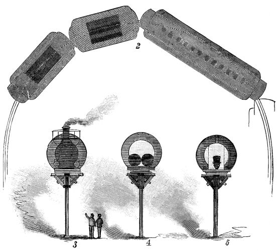
In the illustration, Fig. 2 is a plan view of a train
on a sharp curve, Fig. 3 is an end view of the track and
the engine, Fig. 4 is a section through tender and track,
and Fig. 5 is a section through the car.
From the foregoing it will be seen that this system is as applicable
for surface as for elevated railroads. It may be more cheaply
built than the ordinary road, as the construction of the rolling
stock allows the contour of the ground to be more closely followed.
As an elevated road in cities, the permanent structure presents
far less obstruction to light and air than the usual form. The
center of gravity of the cars and engine is brought as low as
possible, thereby lessening the effect of leverage caused by wind
pressure. The smooth, even surface of the exterior of the entire
train serves to decrease the resistance to the wind, and permits
a high rate of speed.
Oddities Page
| Contents Page
|