|
Trial of Maxim's Steam Flying
Machine
Scientific American—September 15,
1894 [From Engineering, London.]
On Tuesday, July 31, for the first time in the history of the
world, a flying machine actually left the ground, fully equipped
with engines, boiler, fuel, water, and a crew of three persons.
Its inventor, Mr. Hiram Maxim, had the proud consciousness of
feeling that he had accomplished a feat which scores of able mechanics
had stated to be impossible. Unfortunately, he had scarcely time
to realize his triumph before fate, which so persistently dogs
the footsteps of inventors, interposed to dash his hopes. The
very precautions which had been adopted to prevent accidents proved
fatal to the machine, and in a moment it lay stretched on the
ground, like a wounded bird with torn plumage and broken wings.
Its very success was the cause of its failure, for not only did
it rise, but it tore itself out of the guides placed to limit
its flight, and for one short moment it was free. But the wreck
of the timber rails became entangled with the sails, and brought
it down at once. The machine fell on to the soft sward, embedding
its wheels deeply in the grass, and testifying, beyond contradiction,
that it had fallen and not run to its position. If it had not
been in actual flight, the small flanged wheels would have cut
deep tracks in the yielding earth.
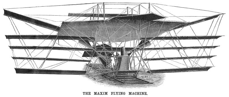
The Maxim flying machine is a large braced structure formed
of steel tubes and wires, and is exceedingly stiff for its weight,
which is about 8,000 lb., including men and stores, At its lower
part it carries a deck, on which the crew stand, where, also,
the boiler, steering wheel, and reservoirs of water and gasoline
are mounted. At a height of some 10 feet above the deck come the
engines, each of which drives a screw propeller of 17 feet 10
inches diameter and 16 feet pitch, working in air. Above the propellers
is the great aeroplane. Smaller aeroplanes project out, like wings,
at the sides, the extreme width being 125 feet and the length
104 feet. There are five pairs of wings, as shown in the illustration,
but the intermediate three pairs are not always used, and at the
time of the accident these were not in place. At that time the
area of the aeroplanes, was 4,000 square feet. With all the planes
in position, the total area is 5,400 square feet. Forward and
aft of the great plane are two steering planes, carried on trunnions
at the sides, and connected by wire strands with a drum on the
deck. By turning this drum the steering planes can be simultaneously
tilted to direct the machine upward or downward, or to keep it
on an even keel.
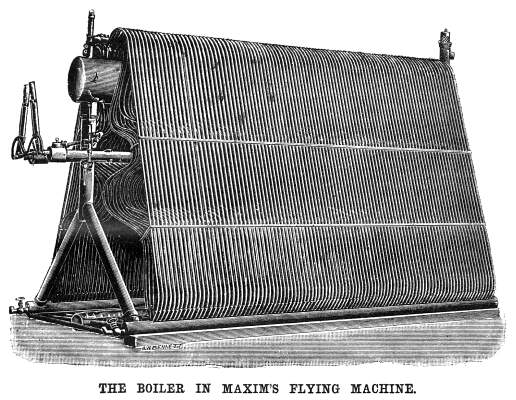
The chief interest centers on the boiler, as, unless this be
made exceedingly light, it is hopeless to expect that the machine
will soar. There is a very close resemblance between the Thornycroft
boiler and Maxim's boiler. In each case there are two wing drums,
connected by a large number of curved tubes with a steam and water
drum, and there are also downcomers to facilitate the circulation.
The casing is also made of straight tubes. In the boiler of the
flying machine a feed heater is placed over the steam drum, but
it is not shown in the engraving. The feed heater is constructed
of steel tubes three-sixteenths inch bore and one-twelfth inch
thick; the water is pumped through It at a pressure 30 lb. higher
than the pressure in the boiler, and is delivered through an injector-like
nozzle into the top of the downcomer pipe. The incoming water
delivers its surplus energy to the surrounding liquid, creating
a rapid and powerful current in the pipe, and consequently maintaining
an active circulation in the small tubes in which the steam is
generated. The feed pumps are placed on the deck beneath the engines,
and are of variable stroke, so as to be adapted to the needs of
the boiler. As they work at high speed, the valves are of large
diameter—larger than that of the plungers. Pounding is prevented
by a rubber bag on the suction and spring pistons on the discharge.
The total quantity of water in the boiler only amounts to 200
lb., so that it is necessary that the amount of feed should be
accurately adjusted. There is a very ingenious water level indicator.
A small pipe is led in a loop from front to back and from back
to front of the furnace. It is then taken to the steam and water
drum, and led backward and forward through that in the same way,
below the water line. The whole is filled with water, and forms
a closed circuit having two loops—one in the furnace and
one in the water. Now, so long as the upper loop is in the water
the pressure does not rise greatly beyond that in the boiler,
because the heat taken up in the furnace is conveyed, by the circulation,
to the water in the drum. But if the water level falls in the
drum, then there is no outlet for the heat; the pressure, consequently,
rises most rapidly, and shows itself on a gauge attached to the
pipe. By this most ingenious device an open-faced pressure gauge
is substituted for the usual gauge glasses. The weight of the
boiler, with casing, feed water heater, dome, and uptake, is 904
lb.; with burner and water it is 1, 200 lb. The heating surface
is about 800 square feet, and the flame surface 30 square feet.
 The fuel burned
in the boiler is gasoline, of a specific gravity of 72 degrees
Baume. It is carried in a copper vessel on deck, and is pumped
through a vaporizer into the furnace. The pipe from the pump is
led into a vessel having a large gasoline burner beneath it. In
this vessel the spirit attains a pressure of 50 lb. on the square
inch, and a corresponding temperature, in which condition it is,
of course, highly inflammable. The gas which it gives off is conducted
by a pipe, passing through the furnace, to a jet, like that of
a Bunsen burner, at the front of the furnace, and in rushing through
it, induces a powerful draught of air, with which it mixes. The
combined charge passes through hollow fire bars, pierced on the
upper surfaces with fine holes, and burns in 7,650 separate flames.
The arrangement is so powerful that the pressure in the boiler
can be raised from 100 lb. to 200 lb. in a minute. The air supply
can be regulated at will, while the expenditure of gasoline automatically
adapts itself to the needs of the boiler. The pressure of the
gasoline vapor acts on a ]ever, which is balanced by a spring.
If the feed is greater than the consumption, the pressure on the
]ever puts a pawl in gear with a ratchet wheel, and, through intermediate
mechanism, works a block along a slotted arm to reduce the throw
of the gasoline feed pumps. If the feed is too small, the opposite
effect is produced, and the throw of the pump increased. The fuel burned
in the boiler is gasoline, of a specific gravity of 72 degrees
Baume. It is carried in a copper vessel on deck, and is pumped
through a vaporizer into the furnace. The pipe from the pump is
led into a vessel having a large gasoline burner beneath it. In
this vessel the spirit attains a pressure of 50 lb. on the square
inch, and a corresponding temperature, in which condition it is,
of course, highly inflammable. The gas which it gives off is conducted
by a pipe, passing through the furnace, to a jet, like that of
a Bunsen burner, at the front of the furnace, and in rushing through
it, induces a powerful draught of air, with which it mixes. The
combined charge passes through hollow fire bars, pierced on the
upper surfaces with fine holes, and burns in 7,650 separate flames.
The arrangement is so powerful that the pressure in the boiler
can be raised from 100 lb. to 200 lb. in a minute. The air supply
can be regulated at will, while the expenditure of gasoline automatically
adapts itself to the needs of the boiler. The pressure of the
gasoline vapor acts on a ]ever, which is balanced by a spring.
If the feed is greater than the consumption, the pressure on the
]ever puts a pawl in gear with a ratchet wheel, and, through intermediate
mechanism, works a block along a slotted arm to reduce the throw
of the gasoline feed pumps. If the feed is too small, the opposite
effect is produced, and the throw of the pump increased.
There are two screws, each driven by a separate compound engine,
having cylinders 5.05 inches and 8 inches in diameter by 12 inches
stroke. The steam is distributed by means of piston valves having
3 inches stroke, and operated by eccentrics. The exhaust steam
is delivered into the air, but Mr. Maxim informs us that he used
successfully an air condenser. This seems to be a necessity, because
the supply of water would prove a serious load. Even to drive
100 horse power would require some 2,500 lb. of water per hour,
which would be a considerable addition to a lengthy trip, especially
if undertaken for warlike purposes in a hostile country.
To supplement, or replace, the safety valve, by-passes are
provided so as to allow live steam to pass directly to the low
pressure cylinders. Instead of blowing off into the air, the steam
is blown past the high pressure cylinders, and the fall in pressure
is made to do work on the exhaust from the high pressure cylinders,
drawing the steam from the high pressure cylinders and driving
it into the low pressure cylinders. The boiler will make more
steam than the engines can take in the usual way.
The boiler pressure, when running, is 320 lb. per square inch,
giving in the high pressure cylinder a differential pressure of
195 lb. and in the low pressure cylinder 125 lb. The cut-offs
are respectively 0.75 and 0.625 of the strokes. In the high pressure
cylinder there is a very large clearance, designed to prevent
injury from water in case the machine should pitch. The actual
horse power delivered to the screws is 363 when the engines are
running at 375 revolutions per minute. Of this, we are informed
by Mr. Maxim, 150 horse power are expended in slip, 133 horse
power in actual lift on the aeroplanes, and 80 horse power in
driving the machine, with its frames and wires, through the air.
The thrust of the screws, when the machine is moored, is 2,100
lb., and when it is running it is 2,000 lb. We give these figures
as they were supplied to us, omitting decimals. The total lift
is something over 10,000 lb. at a speed of forty miles an hour
and with the aeroplanes making an angle of about 7.25 degrees
with the horizontal.
Related Page | Contents Page
|