The Westinghouse Interlocking Switch
and Signal System
Scientific American—May 3, 1890
Some weeks ago we illustrated the electro-pneumatic block system
of train signaling. In our present issue we present our readers
with illustrations of some of the salient points of the Westinghouse
interlocking switch and signal mechanism for use in 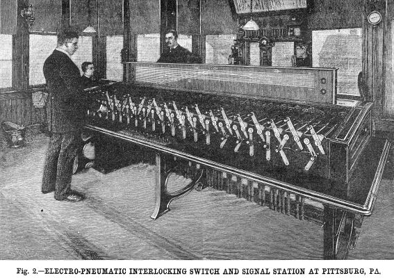 train
yards. It includes three operating agencies, electricity, pneumatic
pressure, and hydraulic pressure. The work of throwing switches
and of setting signals at safety is done by pneumatic pressure.
The valves for regulating its action on signals are worked by
electricity exactly as in the block system already described.
The valves for regulating its action on switches are moved by
hydraulic pressure. train
yards. It includes three operating agencies, electricity, pneumatic
pressure, and hydraulic pressure. The work of throwing switches
and of setting signals at safety is done by pneumatic pressure.
The valves for regulating its action on signals are worked by
electricity exactly as in the block system already described.
The valves for regulating its action on switches are moved by
hydraulic pressure.
Referring to the perspective view of the switch board, it will
be seen to be a case upon whose front are two rows of handles.
These handles, when moved by the operative, turn through an arc
of a circle long vulcanite-covered spindles that run to the back
of the case. These spindles are numbered in pairs of similar numbers,
those to the left are rotated by the lower handles, those to the
right by the upper handles. On the rear end of each spindle is
a quadrant with locking detent, worked electrically. The upper
row of handles operates the switches; the lower row operates the
signals.
At the rear of each switch spindle, that is to say of every
second one, is a three-way cock attached directly to the spindle,
and therefore turned by the upper handle appertaining to the spindle
in question. This cock is a part of the hydraulic system. Turned
to the right, it operates by hydraulic pipe connections a valve
in the neighborhood of a switch which may be a mile or more distant.
The operation of this valve, which is connected to pneumatic pipes,
admits compressed air to the actuating cylinder and piston, and
throws the switch in one or the other direction. The switch-throwing
mechanism will be described later on.
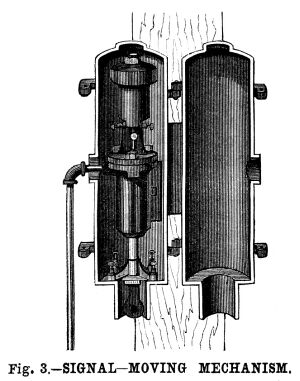 When a current of electricity
is passed through the actuating magnet of the signal-moving mechanism,
Fig. 3, which also may be at any distance, it opens a pneumatic
valve, admitting air to the signal-actuating cylinder, placed
on the semaphore post. The piston is forced outward and the semaphores
are depressed to the safety position. This current is sent through
the switch board, when the handles are set in proper position
therefor. On each of the vulcanite-coated spindles are placed
strips of platinum, and between the spindles are pairs of contact
springs. These, with their connections, can be arranged in any
way whatever to suit the conditions of the case. The circuit,
including the semaphore magnet, is completed through one or more
of these spindle connections. Hence the setting of any given semaphore
at safety may be made to depend upon one or more switch movements,
as necessary. After the switch handles in its series are properly
set, they complete their part of the circuit by means of the platinum
strips and springs. Then the final turn of the signal handle moves
its spindle into position and the circuit is completed, and the
semaphore descends to "safety." When the switches are
to be changed, the signal circuit has first to be broken. This
permits the air valve to close automatically, and the semaphore
rises by the influence of its counterweights to "danger."
The switches can then be moved as required. At the bottom of each
signal-moving mechanism Fig. 3, is a circuit closer. This keeps
a circuit closed as long as the semaphore is at danger. It is
an independent circuit and works the locking of one of the quadrants
on the rear of the signal handle spindles. When a current of electricity
is passed through the actuating magnet of the signal-moving mechanism,
Fig. 3, which also may be at any distance, it opens a pneumatic
valve, admitting air to the signal-actuating cylinder, placed
on the semaphore post. The piston is forced outward and the semaphores
are depressed to the safety position. This current is sent through
the switch board, when the handles are set in proper position
therefor. On each of the vulcanite-coated spindles are placed
strips of platinum, and between the spindles are pairs of contact
springs. These, with their connections, can be arranged in any
way whatever to suit the conditions of the case. The circuit,
including the semaphore magnet, is completed through one or more
of these spindle connections. Hence the setting of any given semaphore
at safety may be made to depend upon one or more switch movements,
as necessary. After the switch handles in its series are properly
set, they complete their part of the circuit by means of the platinum
strips and springs. Then the final turn of the signal handle moves
its spindle into position and the circuit is completed, and the
semaphore descends to "safety." When the switches are
to be changed, the signal circuit has first to be broken. This
permits the air valve to close automatically, and the semaphore
rises by the influence of its counterweights to "danger."
The switches can then be moved as required. At the bottom of each
signal-moving mechanism Fig. 3, is a circuit closer. This keeps
a circuit closed as long as the semaphore is at danger. It is
an independent circuit and works the locking of one of the quadrants
on the rear of the signal handle spindles.
This, in connection with our former article, is enough to show
how the signals are operated. The switch-throwing mechanism has
now to be described. This is placed by the side of the track,
near the switch. It is shown in Fig. 1. The hydraulic tubes, c
c, connect with two cylinders, b b, and force the pistons
one way or the other, according to the position of the three-way
cock in rear of the switch board. At B is a reservoir, kept charged
with compressed air by the regular air pipe, D. At E is a D-valve,
exactly such as used in a steam engine, and which admits the compressed
air into either one of the pipes, d d, and puts the other
one of these pipes in communication with the open air. At A is
a double cylinder with two pistons, connected by a rack and working
a pinion. The partial section is shown in the upper left hand
corner of the cut, in which K is the rack and A is the pinion.
The air admitted by one of the pipes, d d, forces the pistons
in one or the other direction, regulated by the D-valve, thus
turning the pinion. As the pinion turns it carries around with
it an arm attached to its spindle, a. In its revolution
through about three-quarters of a circle the pinion has to successively
perform the following operations: 1. To withdraw the locking bolt,
H, from the hole in the locking bar, N; 2, throw the switch, by
moving the rod, M; 3, return the locking bolt, H, to the other
hole in the locking bar, N.
 Referring to the sectional view,
H is the locking bolt, N the locking bar, and M is the switch
rod. If air is admitted to the right hand end of the cylinder,
the other end communicating with the open air; the pistons will
move to the left. The movement of the pinion may be divided into
three phases, indicated by the dotted lines. Moving from 0 to
1 it withdraws the lock bolt, but practically does not move the
switch bar, or at least only back and forth through the versed
sine of the arc described by the crank pin between 0 and 1. From
1 to 2 the relations are changed; here the switch rod is moved
through a longer distance, corresponding to the chord of the arc,
1-2, throwing the switch, while the lock bolt is only drawn back
and pushed forward a trifle corresponding to the versed
sine of the same arc, 1-2. From 2 to 3 the first relations are
re-established; the lock bolt is thrust forward into the hole
in the lock bar and the switch is hardly moved at all. A detector
bar is worked simultaneously with the lock bolt by means of the
rod, F, of the perspective drawing. Referring to the sectional view,
H is the locking bolt, N the locking bar, and M is the switch
rod. If air is admitted to the right hand end of the cylinder,
the other end communicating with the open air; the pistons will
move to the left. The movement of the pinion may be divided into
three phases, indicated by the dotted lines. Moving from 0 to
1 it withdraws the lock bolt, but practically does not move the
switch bar, or at least only back and forth through the versed
sine of the arc described by the crank pin between 0 and 1. From
1 to 2 the relations are changed; here the switch rod is moved
through a longer distance, corresponding to the chord of the arc,
1-2, throwing the switch, while the lock bolt is only drawn back
and pushed forward a trifle corresponding to the versed
sine of the same arc, 1-2. From 2 to 3 the first relations are
re-established; the lock bolt is thrust forward into the hole
in the lock bar and the switch is hardly moved at all. A detector
bar is worked simultaneously with the lock bolt by means of the
rod, F, of the perspective drawing.
Referring again to the cut of the switch board, a series of
studs or latches are seen projecting through holes below the switch
handles. These, if moved upward, catch the lower projecting ends
of the switch handles. They are raised and lowered by the agency
of the signal handles. As each of these is moved it throws a notched
bar that runs parallel to the face of the case to the right or
left. The bar, according to the arrangement of the notches, throws
upward or permits to drop any one or more of the latches. When
raised a latch locks the lever above it, when depressed it frees
it. Thus a mechanical interlocking of switch and signal handles
is provided that by different disposition of notches may make
the movements of one or more switch handles depend upon the movements
of any given signal handle.
On the rear end of each signal spindle on the switch board
is a quadrant which swings to right or left as the spindle is
rotated. This has teeth in which a latch engages. This latch is
operated by an electro-magnet in the rear included in the independent
signal circuit just described. When the signal is at "safety,"
this circuit is open, and the magnet not attracting its armature,
the latch, by gravity, locks the quadrant as to allow only a small
degree of movement to the signal handle with its spindle. This
movement is enough to close the main circuit and thus release
the semaphore, which rises to "danger," but not enough
to lower the interlocking latch or latches projecting from the
front of the case, until the semaphore has risen the full distance
to "danger." As it reaches this position the auxiliary
or locking circuit is closed, the magnet attracts its armature,
drawing the quadrant latch out of engagement with the quadrant,
and the handle can now be swung clear over, unlocking the switch
handles dependent upon it.
On the rear end of the switch spindle in the switch board are
similar quadrants, whose locking latches are actuated by an electro-magnet
connected with the circuit breaker on the switch-throwing mechanism.
At the end of the locking bolt, H, of this mechanism, Fig. 1,
is a circuit opener. When the bolt is in place and the switch
locked as shown, the circuit is open. This opener is in circuit
with the electro-magnet back of and actuating the quadrant-locking
latch appertaining to its own spindle on the switch board. This
is so constructed that a limited movement only is allowed when
the circuit is open. This movement is enough to turn the three-way
cock. The switch begins to move. As the locking bolt, H, Fig.
1, comes back, the circuit closes. The magnet attracting its armature
unlocks the quadrant and instantly relocks it. This is done so
quickly that the handle cannot be moved during the change. The
switch continues its movement. As it is thrown and locked, the
circuit opens, the quadrant is free, and the handle can be swung
clear over. Its first movement was only sufficient to open the
cocks, but not enough to close the signal-actuating circuit by
the strips of metal on its spindle. This is done by the second
motion. Hence as the signal cannot be moved until this circuit
is closed, and as a semaphore cannot be set at safety without
this closing of circuit, the protecting semaphore cannot be set
at "safety" until all the switches in its system have
been completely thrown and locked by the regular locking bolt.
Above the case containing the switch and signal handle mechanism
and connections, and facing the operator, is a miniature model
of the tracks and switches controlled by the switch board. The
model has movable switches, so that at a glance the operator can
see what position every switch in the system occupies. An annunciator
drop is also placed in view of the operator. This is worked electrically
by any train approaching the system, which train causes a bell
to ring and also drops the shutter when it is within a mile of
the track yard.
Safety Devices
| Contents Page
|