A NINETY-SIX TON ELECTRIC
LOCOMOTIVE
Scientific American—August 10,
1895
With the view, principally, of escaping the nuisance of smoke
and gases from a steam locomotive in drawing passenger trains
through a long tunnel, the Baltimore & Ohio Railroad, with
the co-operation of the General Electric Company, has brought
into its service a powerful electric engine, illustrated on our first page. Three
of these electric locomotives were ordered, and one of then has
for the past few days been doing duty conveying passenger and
freight trains through a tunnel 7,339 feet long, commencing at
the Camden Street depot in the city of Baltimore, and over tracks
at each end of the tunnel, which brings the total haulage by electric
traction up to about three miles. The service calculated upon
from these electric locomotives is the transfer of about 100 trains
each way daily, each passenger train having a maximum weight of
500 tons, including the steam locomotive connected with the train,
to be moved at a speed of 35 miles an hour, and freight trains,
weighing 1,200 tons each, to be moved at a speed of about 15 miles
an hour on an 0.8 per cent grade.
The powerful machine which has been constructed for this work
bears with its entire weight of 96 tons, or 192,000 pounds, on
its eight driving wheels, which is considerably more than twice
the weight on the driving wheels of the heaviest steam locomotive.
It has two trucks and eight driving wheels of a diameter of 62
inches each outside of the tires, the wheel base of each truck
being 6 feet 10 inches; the length over all, 35 feet; and the
height to top of cab, 14 feet 3 inches.
The cab is of sheet steel, sheathed inside with wood, and is
in two parts, each supported upon one truck. There is a sloping
shield on each side of the cab, forward and aft, one shield carrying
a headlight and bell and the other a headlight and whistle.
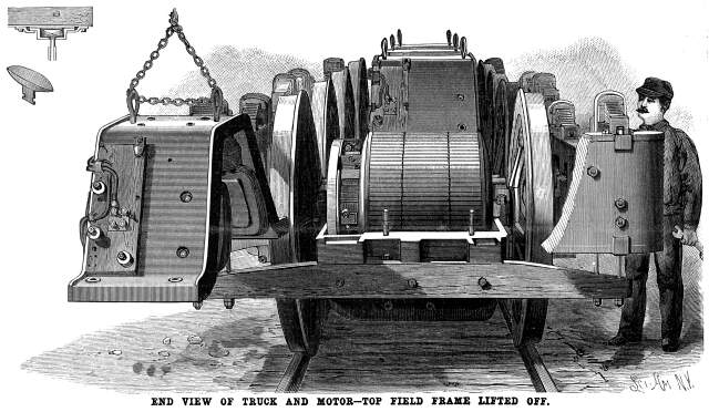 There are four motors, two to each
truck, or one to each axle, and a good deal of the detail of one
of the motors is shown in one of our views, the top field frame
being lifted away from the armature and the bottom field frame
in position. The driving gear consists of a cast steel spider
shrunk on and keyed to a cast steel driving sleeve, forming the
core of the armature, each arm of the spider having a double rubber
cushion with a chilled cast iron wearing cap, the cushion being
forced into the arms of the spider and the cap, and the arms of
the spider being thus held in engagement with the spokes of each
driving wheel. There are four motors, two to each
truck, or one to each axle, and a good deal of the detail of one
of the motors is shown in one of our views, the top field frame
being lifted away from the armature and the bottom field frame
in position. The driving gear consists of a cast steel spider
shrunk on and keyed to a cast steel driving sleeve, forming the
core of the armature, each arm of the spider having a double rubber
cushion with a chilled cast iron wearing cap, the cushion being
forced into the arms of the spider and the cap, and the arms of
the spider being thus held in engagement with the spokes of each
driving wheel.
The motors are supported on carriers bolted to the field magnets,
and rest in adjustable hangers carried on half elliptical springs
placed on top of the frame and bumpers. Each motor has six poles
and six sets of carbon brushes, the latter being connected to
a yoke revolving through 360 degrees, and readily accessible.
The field spools are incased in sheet iron cases and fitted over
the pole pieces bolted to the field frame.
The armatures are built of sheet-iron disks, series-drum wound,
and known as ironclad, each insulated winding being embedded in
an insulated slot cut into the outer surface of the armature body,
and held by a wooden key. The armature, with the commutator, is
mounted upon and keyed to the hollow sleeve carried on the journals
on the truck frame. The inside 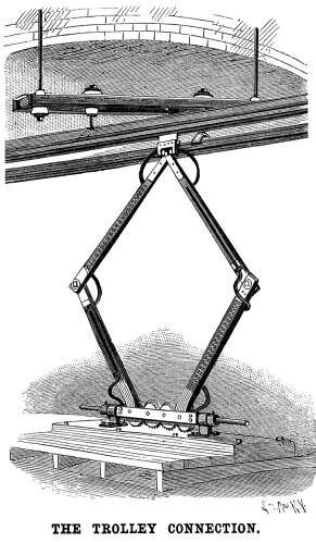 diameter
of the sleeve is about two and a half inches larger than the axle,
and when normally placed the motor rests in a position concentric
to the axle, the clearance between the axle and the sleeve, allowing
a flexible support, and the rubber cushions, permitting the armature
to run eccentric to the axle when the motor departs from its normal
position on account of unevenness in the track. As will be seen
by our illustration, the field frame is readily removable for
inspection or repairs. diameter
of the sleeve is about two and a half inches larger than the axle,
and when normally placed the motor rests in a position concentric
to the axle, the clearance between the axle and the sleeve, allowing
a flexible support, and the rubber cushions, permitting the armature
to run eccentric to the axle when the motor departs from its normal
position on account of unevenness in the track. As will be seen
by our illustration, the field frame is readily removable for
inspection or repairs.
The trolley support, shown in one of our views, is diamond
shaped and compressible, contracting and expanding as may be necessary,
and leaning to one side or the other as the locomotive runs on
one side or the other of the overhead conductor. Contact with
the conductor is made by a sliding, shuttle-like, brass shoe,
shown in a small figure, and the current is brought to the locomotive
by cables connected to the shoe and fastened to the trolley support.
The conductor is a simple form of iron conduit or trough, erected
overhead on trusses outside the tunnel, and in the tunnel attached
to the crown of the arch. It is formed of 3 inch iron Z
bars three-eighths-inch thick, riveted to a cover plate ¼
inch thick and 11½ inches wide, and is made in sections
30 feet long, weighing about 30 pounds per foot. The insulation
of the conductors is effected by conical porcelain insulators
supported in transverse frames, and the supports of the frames
are themselves similarly insulated where they are secured to the
arch of the tunnel, thus affording a double insulation. The feeder
cables are of bare standard copper of sixty-one strands each of
1,000,000 circular mils (one inch) cross section.
Each motor is rated at 360 horse power and takes a normal current
of 900 amperes at a pressure of 700 volts. The controlling devices
and measuring instruments occupy the interior of the cab, the
controller being of the series parallel type. Above the controller
are the instruments which tell the driver the amount and pressure
of the current the motors are taking, and a slot in the floor
enables him to keep his eye on the commutators. The reversing
lever projects through the upper plate of the controller cover,
and the resistances are placed around the frame beneath the floor
of the cab. The locomotive is equipped with a 1,200 to 3,500 ampere
automatic circuit breaker and one 2,000 ampere magnetic cut-out,
a 5,000 ampere illuminated dial Weston ammeter, and one illuminated
dial Weston voltmeter. The compressed air for the whistle and
brakes is supplied by an oscillating cylinder electric air pump,
the air tanks being placed at each end of the complete locomotive.
The interior of the cab is illuminated by clusters of incandescent
lights.
The power house, which is also equipped with an electric lighting
plant for lighting the tunnel, is in the immediate neighborhood
of the tunnel entrance, and is 30 feet high and 322 feet long.
It has an engine room 223 feet long by 57 feet wide, and the dimensions
of the boiler house are 98 x 69 feet. In the latter, in six batteries,
are twelve 250 horse power Abendroth & Root water tube boilers.
Five engines and generators have been provided for, and four are
now in place. The engines are of the tandem compound Reynolds-Corliss
type, and have 24 and 40 inch cylinders. Directly coupled to them
are 500 kilowatt General Electric multipolar generators, adapted
to run with the engine at 110 revolutions a minute, and from these
generators the current is taken over cables of 1,000,000 circular
mils (1 inch) cross section to a switchboard on a platform at
the south end of the engine room. From the positive receiver or
bus on the switchboard eight cables of stranded copper pass to
an overhead structure immediately outside the power horse, where
connection is made to three feeder cables and to an overhead conductor.
The negative bus is similarly connected to the rails, which are
double bonded with No. 0000 wire, and also to return cables laid
in a wooden box between the tracks.
The tunnel, for use in which this locomotive was built, runs
under Howard Street, one of Baltimore's principal thoroughfares,
and was driven without any interference to the surface traffic,
the vertical shafts being sunk to the tunnel through the cellars
of houses along its line. The only severe cave-in occurred in
the vicinity of the Baltimore City College, which was ruined.
A new college was built by the contractors on the site of the
collapsed building. Work on the tunnel was begun in September,
1890, and it was finished early this year. It is 27 feet high
and 22 feet wide, and cost $7,500,000.
Further particulars of this remarkable electrical equipment
will be found in the current issue of our SUPPLEMENT.
Stories Page | Contents Page
|