EXCAVATING AND PIPE LAYING APPARATUS
IN USE ON THE BROOKLYN AQUEDUCT
Scientific American—January 3, 1891
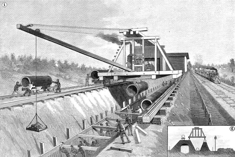
Fig. 1—Excavating and Pipe Laying Plant
at Work —— Fig.2—Section of Aqueduct, New Pipe
Line, and Pipe Laying Plant
The operation of laying large pipe lines has hitherto been
conducted by rather primitive appliances. The operations have
generally been to a great extent manual, and little more than
a derrick placed over the trench for swinging the pipes into place
has been used in the way of machinery. The labor of laying such
mains has been very severe, and progress necessarily slow, as
the work is limited to one point of attack. To secure a consecutive
line without sleeve connections the work must be advanced length
by length, always in the same direction and without intermediate
portions being laid in advance. The apparatus we illustrate has
been used with great success upon the Brooklyn, N. Y., water works,
in laying a new line of forty-eight inch pipes. As the sections
or lengths of pipe weigh from 7,000 to 8,000 pounds each, the
capacity of the machine has been somewhat severely tested. It
has, however, worked most successfully, laying from two hundred
to three hundred feet per day.
The apparatus consists in general of a hoisting apparatus and
crane followed by a lead-melting plant, all moving over the trench.
The two are separate and independent of each other's movements.
They are carried by rails, a single line of which runs along each
side of the trench. In advance of the whole arrangement the excavation
is kept in progress. The trench diggers work as long as practicable
by throwing the earth out by hand. As the depth increases, the
crane carried in advance of the hoisting plant is brought into
play. It is used to elevate the earth from the trench and to swing
it to one side. This operation is shown in Fig. 1 of the engraving.
As fast as necessary, the apparatus is moved forward on the rails
by pinch bars.
Along one side of the trench a portable railroad has been laid.
This serves for cars to run upon to carry off the dirt from the
excavation where necessary, and to bring pipes to be laid in the
trench. In Fig. 2 of the engraving the relations of trench, pipe-laying
plant, and portable railroad are clearly shown. Below the pipe-laying
apparatus the new line of water main is indicated lying at the
bottom of the excavation.
The pipes, as fast as required, are run up to the scene of
operations upon the portable railroad. The hoisting apparatus
consists in general terms of a rectangular platform carried on
four wheels and extending over and across the trench. Through
its floor a longitudinal opening is arranged, directly over the
center of the excavation, large enough for a pipe to pass through
in a horizontal position. The superstructure serves as support
for the jib tackle of the crane and to carry pulleys, etc., for
handling the pipe. As the length of pipe is run alongside, skids
or short timbers of wood are laid from the car to the platform,
and a pair of skids are also laid across the opening over the
axis of the trench. Two or more ropes are brought from the platform
to the car, passing under the pipe and then partially around and
over it, returning to the upper framework. At this point they
pass through pulleys and are brought to the floor, where there
is a steam windlass, which is seen mounted on the platform. On
drawing in the ropes, the pipe, it is obvious, will be rolled
up the inclined plane formed by the skids, and can be brought
directly over the trench. The arrangement is what seamen call
a common "parbuckle." It is often used in the city in
lowering heavy barrels into cellars.
Slings are then placed around the pipe now lying on the skids
over the aperture. Tackle is hooked on, and it is lifted a little
by the steam windlass, and the skids are withdrawn. It is then
lowered into the trench. This stage of operation is shown in the
cut. As it descends, the pipe layers guide it into position. Its
small or spigot end is entered into the hub or socket of the preceding
length, and it is blocked up in a horizontal position iii line
with the work. This ends this stage of operations.
The joint has next to be calked with oakum. This is driven
by hand with a calking iron. It extends all around the pipe within
the hub, and is of as even thickness, as possible. It forms a
base for the lead, which latter is the actual joint-making material.
It should be noted that there is a slight space left between the
abutting ends of the pipe to allow for changes of temperature.
To complete the joint melted lead has to be introduced into
the space in front of the oakum and the lead in turn has to be
calked. As the apparatus just described is moved forward, the
lead-melting plant seen in its rear is moved into its place. This
consists of a house with furnace and lead pot, ladle, and crane.
Its interior is shown in Fig. 3, the men being engaged in lowering
a ladle full of melted lead. Next to the large furnace is a smaller
circular furnace. This is used to keep the ladle hot when it is
not in use.
The lead is lowered, as shown, into the trench, where it is
received by the pipemen and poured into the joint, as shown in
Fig. 4. Before doing this a band of iron hinged at the bottom
is placed around the pipe and bolted at the top, so as to inclose
the annular space in front of the oakum. A clay mouth or funnel,
Fig. 5, is arranged for the lead to be poured into. The connection
of two pipe ends, hub and socket, with their oakum and lead filling,
and with the band in place, is shown in the small sectional view
at the foot of the cut.
The lead at once solidifies. The band is removed, and the calkers
attack the lead with large-faced calking irons and hammers and
drive it home. This operation expands the lead and makes it fill
the joint perfectly.
The metal being somewhat yielding does not form too rigid a
connection, and allows for changes of temperature. In spite of
numerous attempts, lead-calked joints have never been displaced.
The trench in rear of the apparatus is filled in as fast as it
progresses, and the work is complete up to that point.
The object of the line is to carry water from the new reservoir
between Rockville Center and Baldwins, on the south side of Long
Island, to the Ridgewood reservoir and new pumping station at
East New York. It will be a pressure line, and will have a capacity
of twenty-five millions of gallons per day. It follows the line
of the old aqueduct for part of the way. The sectional view, Fig.
2, shows the aqueduct full of water on one side of it. The aqueduct
embankment is thus, in part, utilized in its construction.
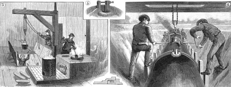
Fig. 3—Interior of Lead Melting Plant
—— Fig. 4—Pouring a Joint —— Fig. 5—Arrangement
of Joint for Pouring
The work is being executed. by Mapes, Crawford & Valentine,
of Brooklyn, N. Y. They are the designers of the ingenious and
efficient apparatus whose results have taken the direction of
greatly accelerating the work we have described.
Stories Page | Contents Page
|