THE LOS ANGELES CABLE
RAILWAY.
Scientific American Supplement, No.
823—October 10, 1891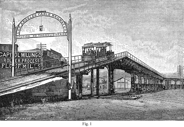
ONE of the most extensive cable-worked railroads in operation
is that of Los Angeles, Cal., its length being about twenty-one
miles of single track, worked by three power stations, all similar
in design. In connection with this road, and serving as feeders,
are twenty-four miles of horse-worked lines. The gauge is 3 ft.
6 in., and the rails, which are of steel, 40 lb. to the yard,
are carried on iron sleepers. The channel in which the cable travels
is made of cement concrete, and the slot rails on the top are
of steel, and weigh 40 lb. per yard. The works on this line are
of considerable interest, and include three viaducts, while the
curves are numerous. One of the viaducts carries the line over
the Santa Fe Railroad and the Los Angeles River, and is of considerable
dimensions. The most important viaduct is that over San Fernando
Street, and of which several views are here given.
 The purpose
of this structure is to carry the cable lines over the Southern
Pacific Railway Company's yards. The plans for it were prepared
by Mr. S. G. Artingstall, of Chicago, and a remarkable feature
about it is that the road is supported on single columns. This
form of construction was necessitated because of a refusal on
the part of both the Southern Pacific Railway Company and the
city authorities to permit the planting of posts where they would
have been necessary if double columns had been used; and we believe
that this viaduct is the only instance in existence where two
tracks are carried on single columns, although in certain parts
of the elevated railway structure in New York a single track is
thus supported. The length of this viaduct is 1,535 ft., of which
50 ft. at each end are occupied by concrete approaches, and the
remaining 1,435 ft. represent the length of the metal work. The
viaduct affords no thoroughfare except for the cable cars, and
in fact no other vehicles could travel over it, as the roadway
is all openwork. The height from the ground to the rail level
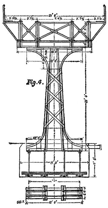
is 25 ft. 9 in., and the width between handrails is 25 ft. The
main posts are 5 ft. wide at the ground line, tapering to 3 ft.
at a height of 14 ft. above ground, and are 22 ft. long. There
are 19 main posts, each weighing 4½ tons, and 10 smaller
posts, 12 in. square and 20 ft. 6 in. long, making 29 posts in
all. The ruling span is 50 ft., but there are two spans of 55
ft., three of 40 ft., one of 30 ft., and one of 20 ft. The main
trusses are of the Warren type, 4 ft. deep, and weighing 100 lb.
per running foot. The approaches are built of 15 I beams, each 25 ft. long, and weighing 50 lb.
per foot. The foundation for each main foot is a solid concrete
block 15 ft. long, 6 ft. wide, and 5 ft. 6 in. deep. Those for
the smaller posts measure 3 ft. every way. The concrete part of
the approaches is 8 ft. high at the highest point and 19 ft. wide.
The grade on the approaches is about 18 per cent. There are two
curves on the viaduct, each of 60 ft. radius to the center line,
and at these points there are braced posts to take the strain,
and the tracks are also carried on double posts at these points
as well as at the approaches, as a precautionary measure. The purpose
of this structure is to carry the cable lines over the Southern
Pacific Railway Company's yards. The plans for it were prepared
by Mr. S. G. Artingstall, of Chicago, and a remarkable feature
about it is that the road is supported on single columns. This
form of construction was necessitated because of a refusal on
the part of both the Southern Pacific Railway Company and the
city authorities to permit the planting of posts where they would
have been necessary if double columns had been used; and we believe
that this viaduct is the only instance in existence where two
tracks are carried on single columns, although in certain parts
of the elevated railway structure in New York a single track is
thus supported. The length of this viaduct is 1,535 ft., of which
50 ft. at each end are occupied by concrete approaches, and the
remaining 1,435 ft. represent the length of the metal work. The
viaduct affords no thoroughfare except for the cable cars, and
in fact no other vehicles could travel over it, as the roadway
is all openwork. The height from the ground to the rail level
is 25 ft. 9 in., and the width between handrails is 25 ft. The
main posts are 5 ft. wide at the ground line, tapering to 3 ft.
at a height of 14 ft. above ground, and are 22 ft. long. There
are 19 main posts, each weighing 4½ tons, and 10 smaller
posts, 12 in. square and 20 ft. 6 in. long, making 29 posts in
all. The ruling span is 50 ft., but there are two spans of 55
ft., three of 40 ft., one of 30 ft., and one of 20 ft. The main
trusses are of the Warren type, 4 ft. deep, and weighing 100 lb.
per running foot. The approaches are built of 15 I beams, each 25 ft. long, and weighing 50 lb.
per foot. The foundation for each main foot is a solid concrete
block 15 ft. long, 6 ft. wide, and 5 ft. 6 in. deep. Those for
the smaller posts measure 3 ft. every way. The concrete part of
the approaches is 8 ft. high at the highest point and 19 ft. wide.
The grade on the approaches is about 18 per cent. There are two
curves on the viaduct, each of 60 ft. radius to the center line,
and at these points there are braced posts to take the strain,
and the tracks are also carried on double posts at these points
as well as at the approaches, as a precautionary measure.
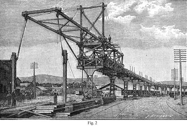
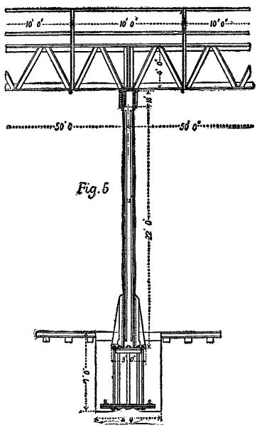
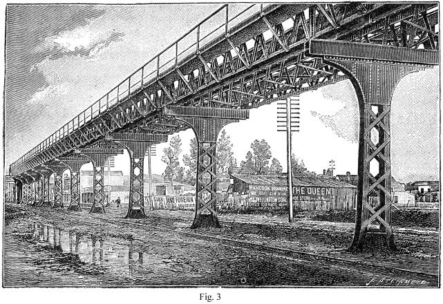 Figs. 2 and
3 are perspective views of different parts of this viaduct and
give a good idea of the construction, while Figs. 4 and 5 are
details of the standards and superstructure. Figs. 2 and
3 are perspective views of different parts of this viaduct and
give a good idea of the construction, while Figs. 4 and 5 are
details of the standards and superstructure.
The entire length of the straight surface tracks of the cable
line is 99,328 ft.; of the viaducts, 4,250 ft.; of bridges, 2,124
ft.; of curves, 2,010 ft.; and of the pits, 562 ft.; making a
total of 108,274 ft. of track, or rather over 20½ miles,
and the construction required 1,444 tons of track and slot rails
and 2,919 tons of iron sleepers.
As already stated, there are three power stations on the system,
all similar in arrangement; they were completed by Messrs. Fraser
& Chalmers, of Chicago, who have supplied engines to several
of the cable companies in that city. The engines in the Los Angeles
stations are compound; the high-pressure cylinder being 26 in.
in diameter, and the low-pressure 42 in. in diameter; the stroke
is 48 in.
They are intended to develop 700 horse power at a speed of
75 revolutions per minute. The high and low pressure cylinders
are set side by side, and the distance between centers is 10 ft.;
the total length of built-up crankshaft is ½ in. over 14
ft. The flywheel is 14 ft. in diameter with rim of 14 in. face
by 18 in. deep, and weighs 36,000 lb.
The first driving shaft of the winding machinery is 18 ft.
2½ in. long, with two journals at the ends and one in the
center between the driving rope pulleys. In the bosses of these
pulleys the shaft is swelled to 16 in. in diameter. The rope wheels,
which are two in number, are 6 ft. 1-and-seven-eighths in. pitch
diameter; they are made in halves, and are each grooved for fourteen
2 in. cotton ropes, the power of the engines being transmitted
to the driven wheels by a system of endless rope transmission
instead of by gearing. The large or driven rope wheels on the
main rope shaft are 25 ft. in diameter, built up of ten segments
each, with a hollow boss in one piece and ten hollow arms of elliptical
section. The shaft which carries these wheels is 16 ft. 1½
inch long, the diameter in the boss of the wheels being 19½
in. This shaft is coupled at each end to the winding shafts, which
are 11 ft. 10¼ in. long, 17 in. in diameter in the center,
and 15 in. at the bosses of the overhung rope drums. These latter
are mounted on each end of the winding shaft, and each has two
grooves for 2 in. cotton ropes, their diameter measured to the
center of the rope being 15 ft. They drive two other rope wheels
or "idlers," which are mounted on their own shaft; these
idlers are of 1 in. less diameter than the driving rope drums,
and the purpose of this is always to keep the cotton ropes taut,
so that the cable itself may not have to perform any of the work
of rotating the idler wheels, the necessary amount of slip required,
as these slightly smaller wheels gain on the drivers, being provided
for in the clutches with which the cable drums are driven. The
cable drums are loose on the extended bosses of the rope wheels;
and are held to these wheels by friction disks, which are tightened
up by eight screws and hand-wheels in each drum. The cable drums
on the winding shaft are 13 ft. in diameter with five grooves
each for 1¼ in. cable, and those on the driven shaft are
of the same diameter, but with four grooves in each. The cable
speed corresponding to 75 revolutions per minute of the engines
is 8½ miles an hour. We believe that this machinery is
working in a very satisfactory manner, and that it reflects much
credit on its builders, Messrs. Fraser & Chalmers.—Engineering.
Stories Page | Contents Page
|