|
Scientific American—April 4, 1903

ELECTRIC TRACK WELDING.
BY WALDON FAWCETT.
Marked improvements have been made during the past two years
in the process of electrically welding rail joints. Although by
the process which has been used since 1897 the breakage on all
welding did not exceed one per cent, the new system has reduced
the percentage of breakage to less than one-tenth of one per cent.
In the city of Rochester, N.Y., where the new process was rarely
employed, more than 5,300 joints were welded during the latter
part of 1901. An examination in the spring of 1902 disclosed only
six broken rails. None of the damaged rails had a joint broken
through the bars or a weld pulled off; practically all of the
breaks occurred through the existence of old bolt or bond holes
beyond the bars.
 The
new plan of welding has been still further improved to meet such
exigencies, and now all welding bars are made long enough to reach
over bolt and bond holes, so that in the future even this source
of breakage will be practically eliminated. The remarkable state
of perfection to which electric track welding has lately been
brought appears all the more marvelous in view of the fact that
in the latest approved method employed, each weld depends on the
judgment of the man making it, and must necessarily remain in
the track and await the strain of winter to disclose defects,
if any exist. Even under these circumstances, however, not one
weld in a thousand fails to successfully stand the actual test. The
new plan of welding has been still further improved to meet such
exigencies, and now all welding bars are made long enough to reach
over bolt and bond holes, so that in the future even this source
of breakage will be practically eliminated. The remarkable state
of perfection to which electric track welding has lately been
brought appears all the more marvelous in view of the fact that
in the latest approved method employed, each weld depends on the
judgment of the man making it, and must necessarily remain in
the track and await the strain of winter to disclose defects,
if any exist. Even under these circumstances, however, not one
weld in a thousand fails to successfully stand the actual test.
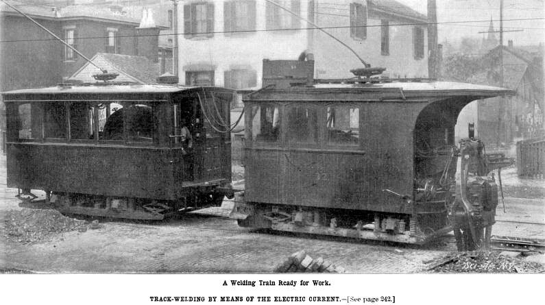
The machinery employed in electric track welding and it is
of a very ingenious character—is mounted on trolley cars
of special design, the running gear of which is provided with
threaded axles, so that the machines can be used to weld track
of almost any gage. The welding of newly-laid rails is done either
before or after the paving is in place, space being left at the
joints to permit the entrance of the welder. When welding is to
be done on rails which have been in place for some time, the paving
is torn up around each joint, and the old plates and bond wires
removed. It is necessary, of course, in such instances, to bring
the rail ends up to the proper grade.
The new method of electrical welding comprises three distinct
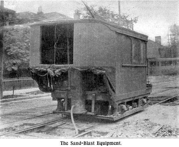
operations. The first step is that of sand-blasting, whereby all
the dirt, rust, and foreign matter is removed from the rails,
at points where welds are to be made, and also from the bars used
in making the joint. Sand-blasting necessitates the employment
of apparatus, including a ten horse power motor driving an air
compressor, an air storage tank, a sand bin and sand mixer. A
hose and nozzle enables the operator to direct the blast of air,
carrying the sand against the rails, so that all foreign matter
is quickly removed.

Two cars are required to carry the apparatus for welding, which
constitutes the second step in the work. The welder itself is
hung from a bail on a, crane, extending out beyond the end of
one car. This crane is so arranged that the jaws of the welder
can engage the sides of the rail, and also shift from one side
to the other, thus enabling work to be carried out on both rails
of the track. The operation of this crane is accomplished by means
of friction clutches, from a shaft in the car, which shaft is
kept running continuously by a five horse power motor.
The motor also drives a small rotary pump, which circulates
water through the welding transformer and the faces of the contacts,
thereby keeping them cool. The water, after it has passed through
the welder, is elevated to a cooling tank on top of the car. It
is of course desirable that this water shall be cooled just as
rapidly as possible, for which purpose a novel plan is employed.
Starting from the middle of the tank, and passing around and around
until the outer circumference of the tank is reached, is a serpentine
partition. A perforated false bottom is provided, through which
air is forced from a powerful blower. The hot water from the welder
passes into the outer portion of the serpentine partition, and
is subjected constantly to the modifying influences of the forced
air. After reaching the center of the serpentine partition, the
cooled water is conducted to one of the tanks in the car.
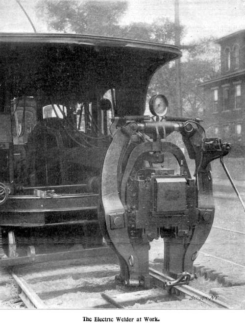
The welding apparatus proper consists of an alternating current
transformer, the primary winding of which is made up of two coils
in parallel, each of forty-four turns. A single loop of copper
of large cross section forms the secondary coil; and the terminals
constitute the contacts or jaws, which engage each side of the
rail, and between which the weld is made. Supporting the transformer
on either side, although insulated from it, are large levers hinged
together at about two-thirds of the distance from the top, which
levers are used to transmit the necessary pressure to the weld.
A hydraulic jack connects these levers at the top. A pressure
of over two tons per square inch is obtained on the rams of the
jack, which are less than four-inch diameter; and inasmuch as
this is increased by the leverage of the arms, the pressure developed
at the weld is in excess of thirty-seven tons.
For making a joint there are employed flat-rolled steel bars
which have on one side, at either end, bosses or projections,
serving as contact points between the bars and the web of the
rail, and confining the welded area of these sections. About the
middle of the bars on the same side with the projections is placed
a flat strip of steel, perhaps one-eighth of an inch in thickness
and one inch wide. The bars are supported on small blocks, and
so placed across the joint that the middle strip engages the web
of both rails. The end welds are horizontal, while the middle
weld is vertical and the full width of the bar.
 The whole operation
of welding is conducted very expeditiously. When the welding train
of two cars is moved up to a joint, the welder is swung into place
and the jaws made to press against the bars on each side of the
rail. The current is then turned on and flows from contact to
contact through the bars and the rail web. By altering the pressure
on the jaws, the resistance of the several junctures is increased,
and the whole is soon brought up to a welding heat. When this
point is reached the current is cut off, and simultaneously the
pressure is brought up to the full amount. Affix the pressure
is loosened, the welder car is moved back, in order to bring the
jaws opposite the extremity of the bars, and here the same process
is repeated, with the addition that when the final pressure is
applied, it is held there and the weld permitted to cool under
pressure, until no glow is apparent. Then the welder is moved
forward to the other end of the bar, and the process is repeated,
after which the welder is swung to the opposite side of the car
and the joint on the other side is welded. The whole operation
of welding is conducted very expeditiously. When the welding train
of two cars is moved up to a joint, the welder is swung into place
and the jaws made to press against the bars on each side of the
rail. The current is then turned on and flows from contact to
contact through the bars and the rail web. By altering the pressure
on the jaws, the resistance of the several junctures is increased,
and the whole is soon brought up to a welding heat. When this
point is reached the current is cut off, and simultaneously the
pressure is brought up to the full amount. Affix the pressure
is loosened, the welder car is moved back, in order to bring the
jaws opposite the extremity of the bars, and here the same process
is repeated, with the addition that when the final pressure is
applied, it is held there and the weld permitted to cool under
pressure, until no glow is apparent. Then the welder is moved
forward to the other end of the bar, and the process is repeated,
after which the welder is swung to the opposite side of the car
and the joint on the other side is welded.
The present plan of holding the pressure after the completion
of the weld increases the strength of the weld very materially.
Only the ends are so treated, the center weld being subjected
to so slight a strain that such a precaution is unnecessary. One
of the improved processes of the new plan of welding grows out
of the discovery that it is advantageous to weld the ends of the
bars while the bars are in an expanded state. By making the center
weld first, and not stopping to cool it under pressure, the greatest
elongation of the bars is, of course, secured. As the bars cool
off, after the ends are welded, they shrink and exert a powerful
pull to bring together the abutting rail ends, thus closing the
slightest opening and leaving practically no joint whatever.
The advance in this direction is of greater significance than
might at first be imagined, for in the manufacture of a continuous
rail, the abutting rail ends, if not brought firmly together,
give the metal in the head of the rail an opportunity to flow
into the opening between the rails. This will in. time cause a
low spot in the head of the rail. The bars being always in a state
of tension, the rail inclosed between the bars is necessarily
in a state of compression; and inasmuch as any contraction of
the rail between the joints will be transmitted to. the end welds,
it is obviously necessary that these latter be as tough as possible,
that they may withstand the strain. The center weld merely contributes
to vertical stiffness, and tends to prevent any movement of the
rail ends.
The current actually used in welding operations by this new
plan approximates from 25,000 to 30,000 amperes at 7 volts. The
car accompanying the welder carries a rotary converter for changing
the direct current from the trolley to an alternating current.
The current in the primary coils of the welder is a 40-cycle alternating,
at 300 volts; and the direct-current side of the rotary converter
is capable of taking from the trolley, current at from 325 to
600 volts. By means of the regulating apparatus, a constant supply
to the welder of 300 volts is maintained, regardless of fluctuations
on the line. At a voltage of 500, about 225 amperes is required
on a line, or, in other words, about 125 kilowatts is required
to make a weld, the time consumed, or rather the interval during
which the current is on, being two and a half minutes.
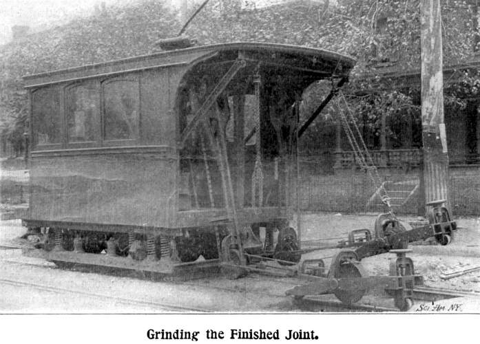
The final operation of welding consists in grinding the head
of the rail to a true surface. There is comparatively little need
for this finishing process where new rails are being welded, but
in old track it is very essential, inasmuch as the receiving rail
is purposely welded higher than the other. The grinder, which
is used to grind out the inequalities in the rail head and bring
it back to a true surface, consists of an emery wheel mounted
on a carriage having two rollers which are about four feet apart.
The carriage is let down on the rail, so that the rollers roll
along the head of the rail, and the emery wheel is thus over the
uneven portion at the joint. A swing frame connects this carriage
with a motor on the car, and the operator is thus enabled to move
the emery wheel back and forth over the joint while the car remains
stationary. A hand wheel enables the emery wheel to be gradually
fed down, and as it is moved forward and back the high places
are ground off until the whole joint is brought to a true surface.
In many respects the operation corresponds to the manipulation
of the ordinary carpenter's plane. When carried on as a continuous
process, only about fifteen minutes are required to complete a
joint; and when operations are conducted day and night, at least
eighty joints are completed in 24 hours.
Track Page
| Contents Page
|


