PROGRESS OF THE GREAT RAILWAY TUNNELS
UNDER THE
HUDSON RIVER BETWEEN NEW YORK AND JERSEY CITY.
Scientific American—November 1, 1890
This great enterprise, after several years of comparative inaction,
has passed into the hands of new managers, having abundant capital,
and under the new auspices the work of construction has been resumed
in the most vigorous and active manner, with promise of early
completion. The affairs are now controlled by London capitalists,
and Sir John Fowler and Sir Benjamin Baker are the consulting
engineers.
The original projector of the Hudson River tunnel was Mr. Dewitt
Clinton Haskin, of New York, formerly of California, who was one
of the active spirits in the construction of the Union Pacific
Railway. He foresaw the great importance and value of this tunnel,
and at his own expense made the preliminary surveys and soundings
necessary to determine the feasibility of the structure and the
proper location of the line.
The work of constructing the tunnels was commenced by Mr. Haskin
in 1874. A circular working shaft 30 feet in diameter was begun,
to be 65 feet deep, the location being on Fifteenth Street, Jersey
City, one hundred feet in side of the bulkhead line of the river.
The shaft had hardly been sunk for half the proper depth when
further progress was enjoined at the instance of the Delaware,
Lackawanna and Western Railroad Co. A long delay ensued but the
right of the Tunnel Co. to proceed was finally established, the
shaft was completed, an enlarged chamber was made at the foot
of the shaft, and from this chamber the headings of two parallel
tunnels were started, on a gentle grade, to descend under the
great river.
Some time after this the sinking of a vertical shaft on the
New York side was begun near the bulkhead at the foot of Morton
street.
The distance between the two shafts is about 5,400 feet. Including
the proper approaches, the total length of the work will be about
12,000 ft.
The illustration below shows a side sectional view of the north
tunnel, the light portion indicating the part that has been completed
up to date, namely, about 2,300 ft on the Jersey side and about
250 ft. on the New York side. The dark line shows the uncompleted
portion.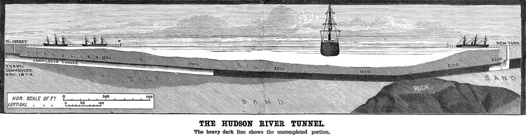
In the construction of the tunnel Mr. Haskin had his own peculiar
views and was his own chief engineer. He insisted that the use
of protecting shields and other devices were unnecessary and,
in fact, a hindrance. Contrary to the recommendations of the engineers,
he relied wholly upon compressed air as a means of temporarily
upholding the walls of the earth until the masonry of the tunnel
could be put in.
It was a bold undertaking, and its failure was confidently
predicted. But Mr. Haskin, went ahead with his remarkable work,
his plan of using compressed air proved valuable, and when worked
in strict accordance with his directions, was successful. Owing,
however, to carelessness of workmen in not watching and stopping
air leaks with sufficient alacrity, it was deemed best, as an
additional element of safety, in 1880, to make use of Mr. J. F.
Anderson's pilot tunnel at the heading. This consisted of a six-foot
iron tube carried into the ground ahead of the tunnel in the middle
of the heading. It was used as a center upon which braces were
placed to hold up the iron plates, the setting of which was begun
at the top of the tunnel. The pilot tunnel also served to indicate
in advance any change in the character of the soil.
Mr. Haskin had completed nearly two thousand feet of the tunnel
when, in 1882, on the decease of one of his principal financial
supporters, the late Trenor W. Park, he was obliged to diminish
his force of workmen and practically to suspend operations until
new monetary arrangements could be made. No man ever battled more
bravely against physical and financial obstacles than did Mr.
Dewitt C. Haskin as the projector and constructor of the Hudson
River Tunnel. As an engineer he deserves high credit, for he has
made known to the profession a mode of using compressed air in
river tunnel work that Is of much value and importance.
Prior to Mr. Haskin's time compressed air had been used in
caissons in the sinking of vertical shafts, by means of which
air it was possible to prevent the rise of water through the soil
composing the bottom of the excavation.
But we believe Mr. Haskin was the first to conceive and put
into actual practice the idea of employing compressed air in a
horizontal tunnel, for the purpose of assisting to uphold the
earth of the side walls, ceiling and heading so that the same
could be excavated and the masonry or iron tunnel put therein.
This method was patented by Mr. Haskin February 3, 1874, and in
his patent be thus expresses his ideas:
"My invention relates more especially to the construction
of tunnels through sands, wet earths under water courses and under
such like conditions where the caving-in of the walls of the excavation
or the infiltration or irruption of water is to be apprehended.
Its object is to effectually prevent such incidents in a cheap
and simple way, to which end my improvement consists in filling
the excavation with compressed air of a density sufficient to
resist the inward pressure during the construction of the shell
or wall of the tunnel.
"The distinguishing feature of my system, however, is
that instead of using temporary facings of timber or other rigid
material, I rely upon the air pressure to resist the caving-in
of the wall or the infiltration of water until the masonry wall
is completed. The pressure is, of course, to be regulated by the
exigences of the occasion and may be varied from anything above
that of' the atmosphere to 50 lb. to the square inch, which is
about as much as the human system will bear with safety. The effect
of such pressure has been found to be to drive water in from the
surface of the excavation, so that the sand becomes dry."
Having thus briefly brought down the history of this important
work from its inception in 1874, let us glance at its present
active condition and the methods for working that have been adopted
by the London company. Mr. Haskin's method of using compressed
air is still used, and is found to be indispensable. But as an
engineering precaution, and to assist in the more rapid prosecution
of the work, the Beach hydraulic shield has been introduced. Furthermore,
iron plates much thicker and stronger than those before used have
been adopted for the outer walls of the tunnel. Our readers are
familiar with the history of this form of shield. It was designed
and first constructed by Mr. A. E. Beach, one of the editors and
proprietors of Scientific American. It was first used in constructing
a short section of the projected. Broadway underground railway
in this city, 1868-69. The two tunnels under the Thames River
and parts of London, for the new London underground electric railway,
shortly to be opened to the public, were built by means of these
shields; also the great railway tunnel under the St. Clair River,
between Port Huron, Mich., and Sarnia, Canada.
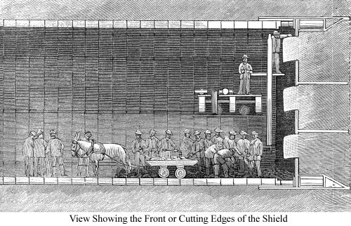 Referring now to our illustration
to the right we give, a perspective front end view of the shield.
(Fig. 1) Referring now to our illustration
to the right we give, a perspective front end view of the shield.
(Fig. 1)
It resembles a gigantic barrel without heads; its front end
is provided with an inclined cutting edge, with horizontal and
vertical braces or stanchions, back of which are strong vertical
bulkheads or diaphragms, in which are a series of doors. Arranged
around within the outer walls of the shield are a series of hydraulic
jacks of great power, all operated by a common pump, but each
jack provided with a stop cock, so that all or any one, or any
desired number of the jacks, may be worked at once, as desired.
A glance at the engravings will show the positions of these jacks.
The shield thus constructed is placed in the heading of earth,
and the front end of the tunnel is covered by and inclosed within
the rear part of the shield. The latter may be said to form a
protecting cap or cover to the front end of the tunnel, and prevents
the caving-in of the earth upon the workmen. When the shield is
to be advanced the hydraulic pump is set in motion 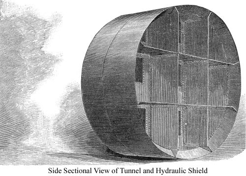 and
the jacks are made to bear with great force against the front
end of the tunnel as shown in Figs. 1, 2, 3. (Left is Fig. 2).
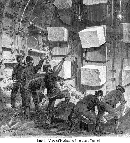
This drives the shield ahead into the clay or silt, which consequently
enters the front of the shield, through the doors before mentioned;
a stream of the silt comes in at each door, and is broken off
into blocks by the men, as shown in our illustrations. The pressure
on the jacks is now stopped and the pistons of the jacks pushed
back within their cylinders, which leaves a free space within
the rear part or hood of the shield, and in this space a new section
of the tunnel is built up and joined to the front end of the tunnel.
The new section now becomes the front end of the tunnel, and against
it the jacks are now pushed to send the shield again ahead. The
extreme front end of the tunnel is thus always protected and covered
by the shield. and
the jacks are made to bear with great force against the front
end of the tunnel as shown in Figs. 1, 2, 3. (Left is Fig. 2).
This drives the shield ahead into the clay or silt, which consequently
enters the front of the shield, through the doors before mentioned;
a stream of the silt comes in at each door, and is broken off
into blocks by the men, as shown in our illustrations. The pressure
on the jacks is now stopped and the pistons of the jacks pushed
back within their cylinders, which leaves a free space within
the rear part or hood of the shield, and in this space a new section
of the tunnel is built up and joined to the front end of the tunnel.
The new section now becomes the front end of the tunnel, and against
it the jacks are now pushed to send the shield again ahead. The
extreme front end of the tunnel is thus always protected and covered
by the shield.
The resistance encountered by the shield arises not so much
from the cling or friction of the silt against the surface of
the shield as it does from the small area of the door openings
compared with that of the entire bulkhead or diaphragm. There
are nine doors or openings in the bulkhead, and consequently nine
streams of silt pour simultaneously into the shield when it is
pushed ahead.
 (Fig. 3) (Fig. 3)
The general method of carrying forward the work is extremely
simple. At 1,250 feet from the shore in the north tunnel from
the Jersey shore is a masonry bulkhead containing the first air
lock. Three hundred and fifty feet beyond this is a second air
lock, and about 1,900 feet from the shaft is still a third air
lock, through which the working chamber or heading is entered.
This air lock consists simply of a boiler shell 6 feet in diameter
by 15 feet long, provided at each end with a 3 by 4 foot door,
opening toward the shaft. Through these pass all supplies and
all excavated material, a car track running from the shaft down
to the heading.
The external diameter of the shield is 19 feet 11 inches, its
length being 10½ feet. The outer or cylindrical portion
consists of two thicknesses of steel plates five-eighths of an
inch thick. The bulkhead, which divides the shell transversely
into two parts, is built of steel five-eighths of an inch thick,
and is placed 5-and-two-thirds feet from the forward edge. In
this division are the nine doors above mentioned. The shield is
also divided horizontally and vertically by two diaphragms built
of double half-inch plates. The inner shell of the shield—for
it must be mentioned that the cylindrical part is formed of two
concentric shells, which are separated from each other a distance
of 1 foot 5 inches—is composed of one-half inch plates, and
it extends from the center bulkhead to within 2-and-one-third
feet of the cutting edge.
These two shells are securely united. Between the shells are
carried the cylinders of sixteen twenty-ton hydraulic jacks. The
plungers of these have a bearing against the rings of completed
plates forming the tunnel proper. Each ring is formed of flanged
cast iron plates 1¼ inch thick, the flanges being 1½
inches thick and 8 and 9 inches deep. The flanges are cast with
holes in order that they may be bolted together.
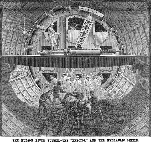 They are placed in position by
a hydraulic segment erector shown in the engraving on the left.
This is carried in the center of a girder spanning the completed
work, and provided at each end with two double-flange wheels which
run upon a track, fitted to brackets held to the flanges of the
rings of plates in position. In this way the girder and the erector
it carries can be moved longitudinally as desired. The frame spanning
the tunnel consists of two girders, each of which carries a cast
iron hydraulic cylinder, the two being counterparts of each other.
These cylinders are six feet long and the rams working in them
are 6½ inches in diameter. To the head of each plunger
is fixed a pulley, 17 inches in diameter. Now, between the rams
is a cast iron drum 2¼ inches in diameter by 12 inches
face. The weight of the cross-head of the plunger is supported
by a pair of 4-inch wheels bearing on a flange of the girders.
A chain passes from a bracket on each ram over the pulley on the
end of the plunger and then to the drum between the cylinders,
the strokes of the plungers being so adjusted that when one is
moving forward the other is moving to the rear or further in its
cylinder. Any movement, therefore, of the rams must of necessity
result in revolving the drum. A shaft seven inches in diameter
connects the drum with the main arm of the erector, which is placed
just outside of the forward girder. This arm is 14½ feet
long and is so mounted that it can be moved in a direction at
right angles to the shaft by means of a double ram placed inside
of it. The erector is controlled from a platform by a pair of
levers, one regulating the pressure to the cylinders on the bridge
girder and thereby revolving the erector as may be necessary,
and the other governing the pressure to the cylinder of the erector. They are placed in position by
a hydraulic segment erector shown in the engraving on the left.
This is carried in the center of a girder spanning the completed
work, and provided at each end with two double-flange wheels which
run upon a track, fitted to brackets held to the flanges of the
rings of plates in position. In this way the girder and the erector
it carries can be moved longitudinally as desired. The frame spanning
the tunnel consists of two girders, each of which carries a cast
iron hydraulic cylinder, the two being counterparts of each other.
These cylinders are six feet long and the rams working in them
are 6½ inches in diameter. To the head of each plunger
is fixed a pulley, 17 inches in diameter. Now, between the rams
is a cast iron drum 2¼ inches in diameter by 12 inches
face. The weight of the cross-head of the plunger is supported
by a pair of 4-inch wheels bearing on a flange of the girders.
A chain passes from a bracket on each ram over the pulley on the
end of the plunger and then to the drum between the cylinders,
the strokes of the plungers being so adjusted that when one is
moving forward the other is moving to the rear or further in its
cylinder. Any movement, therefore, of the rams must of necessity
result in revolving the drum. A shaft seven inches in diameter
connects the drum with the main arm of the erector, which is placed
just outside of the forward girder. This arm is 14½ feet
long and is so mounted that it can be moved in a direction at
right angles to the shaft by means of a double ram placed inside
of it. The erector is controlled from a platform by a pair of
levers, one regulating the pressure to the cylinders on the bridge
girder and thereby revolving the erector as may be necessary,
and the other governing the pressure to the cylinder of the erector.
If what we may term the gripping end of the arm be deflected
until it is directly over one of the plates to be lifted into
place, and is then moved downward so that a bolt can be passed
through two arms on its end, which are placed each side of a perforated
lug cast in the middle of the plate, the erector is in position
to lift one plate. The arm of the erector is then moved upward
until it is known that the plate will clear any obstruction, and
is then swung in a circle whose plane is vertical until it is
in a line with the space to be occupied by that plate. It is then
so moved as to place the plate in position, when it holds it there
until the bolts have been inserted. The whole operation is extremely
simple, and is clearly shown in the cut on the preceding page,
and, so far, has been found to work to good advantage.
The silt which comes through the shield is taken back in a
car to a hydraulic elevator, where it is lifted about twelve feet
to the level of the track extending up through the tunnel. The
tunnel is left a little over half full of material, it being deemed
more economical and expeditious to let this remain, and remove
it after the completion of the work.
The air pressure now used is between 35 and 40 pounds to the
inch, and serves the important purpose of counterbalancing the
water pressure on the shield, thus enabling the jacks to push
the shield ahead.
So far no trouble has been experienced in keeping the work
to line. A change of direction of movement is effected by employing
those jacks opposite to which it is desired to deflect the shield.
By using the jacks on the right hand side, the shield can be made
to move further toward the left. The average rate of progress
is about four feet a day, the work being carried on in three shifts
of eight hours each.
The personnel of the tunnel is as follows: Sir John
Fowler and Sir Benjamin Baker, who built the Forth Bridge, are
the consulting engineers; Mr. Wm. R. Hutton, under whose direction
the Washington Bridge over the Harlem was constructed, is chief
engineer; Mr. E. W. Moir, who had charge of the erection of one
cantilever span of the Forth Bridge, is engineer for the contractors,
Messrs. S. Pearson & Son; Mr. C. A. Haskin, a son of the projector
of the tunnel, is the superintendent.
The form of Beach shield here used and the hydraulic gear were
designed by Mr. E. W. Moir, under Sir Benjamin Baker's directions.
The erector was also designed by Mr. Moir. All the parts were
constructed by Sir William Arrol & Co., at their Glasgow shops.
Tunnel Page
| Contents Page
|