THIRD RAIL ELECTRICAL
EQUIPMENT OF THE
NEW YORK, NEW HAVEN AND HARTFORD RAILROAD.
(Continued from SCIENTIFIC AMERICAN
of June 12, 1897.)
In our previous notice of the electrical equipment of a portion
of the lines of the New York, New Haven and Hartford Railroad
we stated that the power house at Berlin was a plain rectangular
structure 106 feet in width by 117 feet long, the sides and one
end being of brick, the other end being temporarily boarded up
until the building shall be extended and completed. The building
is divided longitudinally by a brick partition wall; the front
portion, or that facing the tracks, is two stories in height,
the engines and dynamos being installed in the upper story and
the heaters and various accessories in the basement. The rear
half constitutes the boiler room. Interior views of these rooms
will be found on the front page of this issue.
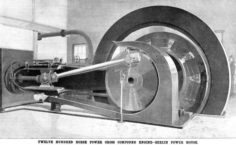
At present the engine room contains a 1,200 horse power engine
of the cross compound type, with a 28 inch by 48 inch high pressure
cylinder and a 48 inch by 48 inch low pressure cylinder. The flywheel
is 18 feet in diameter and weighs over 52 tons. The engine dynamo
shaft is of hollow steel, and the engine is direct connected to
a General Electric Company's standard 10 pole, 850 kilowatt generator
of the ironclad type.
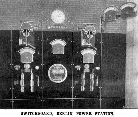 The switchboard shown in the accompanying
illustration is set in a bay built out on the front of the building.
It is of the standard panel type of the General Electric Company
and contains seven panels, of which three only are at present
equipped. Two of these are generating panels and the third is
a totalizing panel. Upon the former are automatic circuit breakers
of extra large size, with magnetic blowout and the usual generator
panel equipment ; the totalizing panel carries a Form G Thompson
5,000 ampere recording wattmeter and an 8,000 ampere station ammeter.
Four cables, each of 850,000 circular mils cross section, run
from the switchboard to the third rail.
The switchboard shown in the accompanying
illustration is set in a bay built out on the front of the building.
It is of the standard panel type of the General Electric Company
and contains seven panels, of which three only are at present
equipped. Two of these are generating panels and the third is
a totalizing panel. Upon the former are automatic circuit breakers
of extra large size, with magnetic blowout and the usual generator
panel equipment ; the totalizing panel carries a Form G Thompson
5,000 ampere recording wattmeter and an 8,000 ampere station ammeter.
Four cables, each of 850,000 circular mils cross section, run
from the switchboard to the third rail.
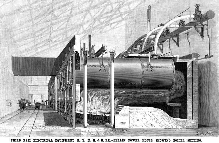
The boiler room contains ten horizontal tubular boilers, which
type has been selected on account of its. "simplicity, high
economy, and general reliability." In setting the boilers,
care has been taken to provide for absolutely free expansion in
all directions, and especially in a direction transverse to the
axis of the boilers. It will be seen from the illustration that
the boilers are suspended from two pairs of I-beams, which
rest upon the brick partition walls, the suspension rods being
linked to straps which are riveted to the shell of the boiler.
The great height (48 inches) from the fire bars to the boiler
is a noticeable feature, and it was adopted in order to secure
a more thorough combustion and a slower passage of the gases to
the uptake. It is claimed that with judicious firing the uptake
temperature has been kept considerably below the normal for this
type of boiler. The grates are designed for burning the half burned
coal known as "sparks," which is recovered from the
fire boxes of the locomotives of the New Haven road. As there
are several hundred tons of this material produced every month,
it can be understood that it is an extremely cheap fuel as delivered
in the bins at the power house. The pipes which lead down through
the partition walls and below the grate are for introducing a
mixture of steam and air to supply the necessary oxygen for combustion.
Each pipe is slightly flaring at the top, and contains an annular
steam pipe perforated on its under side. The gases pass from the
boiler tubes to a rectangular flue, which extends the full length
of the nest of boilers, and delivers into a cross flue 5½
feet wide by 8 feet deep, which leads to a chimney 125 feet, in
height on the outside of the building. The "sparks"
is delivered into a row of bins located on the outside of the
boiler house, and from these it is drawn off as required into
small trucks, which run on a track parallel with the wall of the
building. From this track it is switched on to another track,
which runs at a convenient distance from the furnaces. The fuel
is shoveled directly from the trucks into the furnace. Swinging
trucks are also provided for carrying away the ashes. Special
care has been taken in designing the boiler fronts, which are
held in place by clamps, and may be taken down separately in a
few minutes by loosening the clamps—an arrangement which
will commend itself to practical men at first sight.
Another point which has received special attention is the arrangement
of the steam piping. Col. Heft does not believe that it is good
policy to put in a costly duplicate system of piping, and he is
of the opinion that satisfactory results may be obtained by exercising
care and good judgment in the design and erection of a single
system. Accordingly, every provision has been made for free movement
of the piping under expansion and contraction. In the first place,
a 20 inch wrought iron header runs the entire length of the boiler
room, at a height of eight feet above the boilers. It has a free
longitudinal movement upon rollers, which are carried upon brackets
attached to the central partition wall of the building. Each boiler
is connected with the header by a heavy seamless copper 9 inch
pipe bent to a radius of 8½ feet. The throttle valves are
placed at the junction of these pipes with the header, the valves
being all of the balanced type. Steam is led to the engine by
12 inch wrought iron pipes with bends of large radius. The piping
of the accessory steam plant is so arranged that the engines may
be run as condensing or non-condensing. Each side of the engine
can be run independently and the feed may or may not be heated,
at the option of the engineer.
In the illustration showing the various car couplings will
be noticed the electrical car coupling or connector-box. In the
earlier experiments considerable trouble was experienced at the
exposed point where the wires entered the motors, and the connector
box was designed to overcome the difficulty. The connection consists
of a hollow brass tube, split at the outer end to give it a tight
grip of the motor wire, and incased in a wooden plug. There are
two of these and they enter a connector box located beneath the
front end of the platform, as shown in the engraving, the box
being closed by a lid when it is not in use.
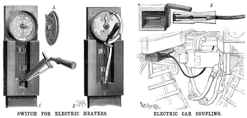
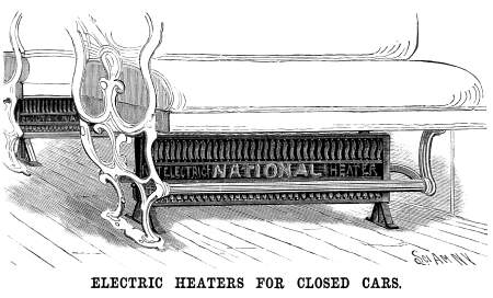
The closed cars are each provided with sixteen electrical heaters,
which are placed beneath the seats as shown in the sketch. The
degree of current and therefore the temperature is regulated by
means of an electrical switch of special construction. There are
four graduations on the dial: full, half, low, and off. The dial,
which is movable, has the brushes attached to its inner face,
and these move upon a series of contacts on the fixed plate. In
order to reduce the spark on opening or closing the switch, the
switch lever is formed separately from the knife, the former being
hinged to the latter near its junction with the switchboard. Normally
the knife is held against the lever by the tension of a plate
spring; but when the lever is pulled open the two are separated,
the knife snapping suddenly against the lever as it leaves the
contacts and reducing the duration of the spark.
 The heaters in each coach are connected
in series with each other and form a complete circuit extending
down on one side of the car and up on the other, in which all
of the sixteen heaters are included. This circuit, known as the
series wire, has no connection with the heat-regulating switch,
neither is the positive (trolley) nor the negative (ground) side
of the current supply permanently connected to any portion of
this circuit. A variable ground and trolley connection is carried
by the regulating switch and can be applied by means of tap wires
to one or more points of the series wire or circuit, according
to the amount of heat required. As the heat generated is directly
proportionate to the amount of current flowing through the wires
of each heater, and as this flow of current is governed by the
combined resistance of the heaters through which the current must
flow, it is but necessary to vary the number of heaters between
a point where the current enters and where it leaves again in
order to regulate the temperature to any desired degree.
The heaters in each coach are connected
in series with each other and form a complete circuit extending
down on one side of the car and up on the other, in which all
of the sixteen heaters are included. This circuit, known as the
series wire, has no connection with the heat-regulating switch,
neither is the positive (trolley) nor the negative (ground) side
of the current supply permanently connected to any portion of
this circuit. A variable ground and trolley connection is carried
by the regulating switch and can be applied by means of tap wires
to one or more points of the series wire or circuit, according
to the amount of heat required. As the heat generated is directly
proportionate to the amount of current flowing through the wires
of each heater, and as this flow of current is governed by the
combined resistance of the heaters through which the current must
flow, it is but necessary to vary the number of heaters between
a point where the current enters and where it leaves again in
order to regulate the temperature to any desired degree.
Electric Article 1 |Lines
West | Stories Page | Contents
Page