|
CHAPTER XVII.
THE VALVE-MOTION.
THE LOCOMOTIVE SLIDE-VALVE.
THE nature of the service required of locomotive engines,
especially those employed on fast-train service, makes it necessary
that the steam-distribution gear shall be free from complication;
and, for convenience in working the engine, it is essential that
means should be provided for reversing the motion promptly, without
endangering the working-parts. The valve-gear should also be capable
of regulating the admission and exhaust of steam, so that the
engine shall be able to maintain a high rate of speed, or to exert
a great tractive force. These features are admirably combined
in the valve-gear of the ordinary locomotive. Designers of this
form of engine have given great consideration to the merit of
simplicity. Numerous attempts have been made to displace the common
D slide-valve, but every move in that direction has ended in failure.
INVENTION AND APPLICATION OF THE SLIDE-VALVE.
The slide-valve, in a crude form, was invented by Matthew
Murray of Leeds, England, towards the end of last century; and
it was subsequently improved by Watt to the D form. It received
but little application in England till the locomotive era. Oliver
Evans of Philadelphia appears to have perceived the advantages
possessed by the slide-valve, for he used it on engines he designed
years before locomotives came into service. The D slide-valve
was better adapted for high-speed engines than any thing tried
during our early engineering days, but it was on locomotives where
it first properly demonstrated its real value. The period of necessity
brought the slide-valve into prominence; and the galaxy of mechanical
genius that heralded the locomotive into successful operation
recognized its most valuable features, and it soon obtained exclusive
possession of that form of engine. Through good and evil report,
and against many attempts to displace it, the slide-valve has
retained a monopoly of high-speed reversible engines.
DESCRIPTION OF THE SLIDE-VALVE.
The slide-valve in common use is practically an oblong
cast-iron box, which rests and moves on the valve-seat. In the
valve-seat, separated by partitions called bridges, are three
ports, those at the ends being the openings of the passages for
conveying steam to and from the cylinders, while the middle port
is in communication with the blast-pipe, which conveys the exhausted
steam to the atmosphere. On the under side of the valve is a semicircular
cavity, which spans the exhaust-port and the bridges when the
valve stands in its central position. When the steam within the
cylinder has performed its duty of pushing the piston towards
the end of the stroke, the valve cavity moves over the steam-port,
and allows the steam to pass into the exhaust-port, thence into
the exhaust-pipe. The cavity under the valve thus acts as a door
for the escape of the exhaust steam. This is a very convenient
and simple method of educting the steam; and the process helps
to balance the valve, since the rush of escaping steam striking
the under part of the valve tends to counteract the pressure that
the steam in the steam-chest continually exerts on the top of
the valve.
PRIMITIVE SLIDE-VALVE.
In its primitive form, the slide-valve was made merely
long enough to cover the steam-ports when placed in the central
position, as shown in Fig. 6. With a valve of this form, the slightest
movement had the effect of opening one end so that steam would
be 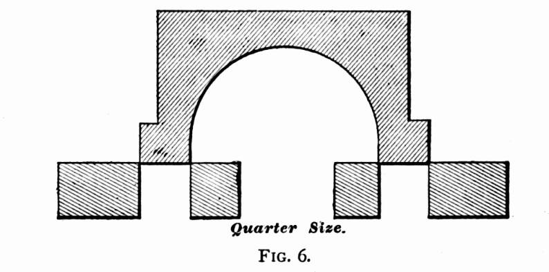 admitted to
the cylinder, while the other end opened the exhaust. By such
an arrangement, steam was necessarily admitted to the cylinder
during the whole length of the stroke; since closing at one end
meant opening at the other. There were several serious objections
to this system. It was very difficult to give the engine cushion
enough to help the cranks over the centers without pounding, and
a small degree of lost motion was sufficient to make the steam
obstruct the piston during a portion of the stroke. But the most
serious drawback to the short valve was, that it permitted no
advantage to be taken of the expansive power of steam. For several
years after the advent of the locomotive, the boiler pressure
used seldom exceeded fifty pounds to the square inch. With this
tension of steam, there was little work to be got from expansion
with the conditions under which locomotives were worked; but,
so soon as higher pressures began to be introduced, the loss of
heat entailed by permitting the full-pressure steam to follow
the piston to the end of the stroke became too great to continue
without an attempted remedy. A very simple change served to remedy
this defect, and to render the slide-valve worthy of a prominent
place among mechanical appliances for saving power. admitted to
the cylinder, while the other end opened the exhaust. By such
an arrangement, steam was necessarily admitted to the cylinder
during the whole length of the stroke; since closing at one end
meant opening at the other. There were several serious objections
to this system. It was very difficult to give the engine cushion
enough to help the cranks over the centers without pounding, and
a small degree of lost motion was sufficient to make the steam
obstruct the piston during a portion of the stroke. But the most
serious drawback to the short valve was, that it permitted no
advantage to be taken of the expansive power of steam. For several
years after the advent of the locomotive, the boiler pressure
used seldom exceeded fifty pounds to the square inch. With this
tension of steam, there was little work to be got from expansion
with the conditions under which locomotives were worked; but,
so soon as higher pressures began to be introduced, the loss of
heat entailed by permitting the full-pressure steam to follow
the piston to the end of the stroke became too great to continue
without an attempted remedy. A very simple change served to remedy
this defect, and to render the slide-valve worthy of a prominent
place among mechanical appliances for saving power.
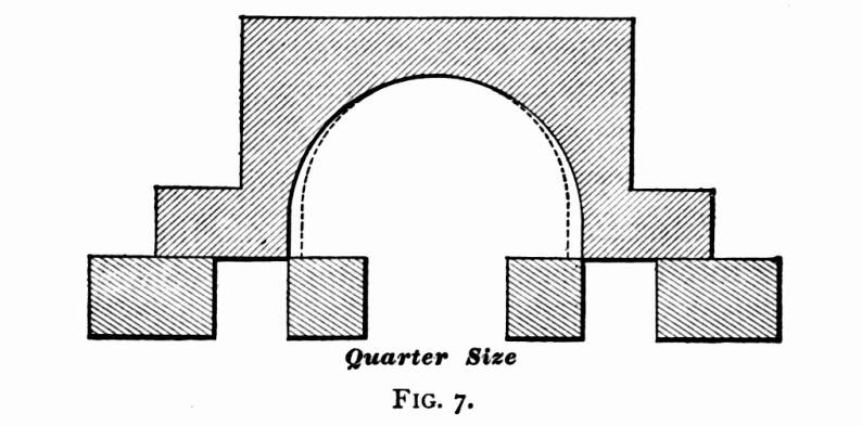
OUTSIDE LAP.
The change referred to, which so greatly enhanced the
efficiency of the slide-valve, consisted in lengthening the valve-face,
so that, when the valve stood in the center of the seat, the edges
of the valve extended a certain distance over the induction ports,
as in Fig. 7. This extension of the valve is called outside lap,
or simply lap. The effect of lap is to close the steam-port before
the piston reaches the end of the stroke, and the point at which
the steam-port is closed is known as the point of cut-off. When
the steam is cut off, and confined within the cylinder, it pushes
the piston along by its expansive energy, doing work with heat
that would be lost were the cylinder left in communication with
the steam-chest till the end of the stroke.
 When a slide-valve
is actuated by an eccentric connected directly with the rocker-arm
or valve-stem, the point of cut-off caused by the extent of lap,
remains the same till a change is made on the valve, or on the
throw of the eccentric, unless an independent cut-off valve be
employed. Locomotives having the old hook motion worked under
this disadvantage; because the hook could not vary the travel
of the valve, which is the method usually resorted to for producing
a variable cut-off. The link and other simple expansion gears
perform their office of varying the cut-off in this way. When a slide-valve
is actuated by an eccentric connected directly with the rocker-arm
or valve-stem, the point of cut-off caused by the extent of lap,
remains the same till a change is made on the valve, or on the
throw of the eccentric, unless an independent cut-off valve be
employed. Locomotives having the old hook motion worked under
this disadvantage; because the hook could not vary the travel
of the valve, which is the method usually resorted to for producing
a variable cut-off. The link and other simple expansion gears
perform their office of varying the cut-off in this way.
SOME EFFECTS OF LAP.
In addition to cutting off admission of steam before
the end of the stroke, lap requires the valve to be set in such
a way that it has also the effect of leading to the exhaust-port
being opened before the end of the stroke. The point where the
exhaust is opened is usually known as the point of release. The
change which causes release to happen before the piston completes
its stroke, leads to the closure of the exhaust-port before the
end of the return stroke is reached, which imprisons the steam
remaining in the cylinder, causing compression. Where a valve
has no inside lap, release and compression happen simultaneously;
that is, the port at one end of the cylinder is opened to release
the steam, and that at the other end is closed, letting the piston
compress any steam remaining in the cylinder into the space left
as piston clearance.
INSIDE LAP.
In some cases the inside edges of the valve cavity
do not reach the edges of the steam-ports when the valve is on
the middle of the seat, but lap over on the bridge a certain distance,
as shown by the dotted lines in Fig. 7. This is called inside
lap, and its effect upon the distribution of steam is to delay
the release. By this means it prolongs the period of expansion,
and hastens compression on the return stroke. Inside lap is an
advantage only with slow-working engines. When high speed is attempted
with engines having much inside lap, the steam does not have enough
time to escape from the cylinders, and the back pressure and compression
become so great as to be very detrimental to the working of the
engine. As locomotive engineers have it, the engine is "logy."
THE EXTENT OF LAP USUALLY ADOPTED.
In locomotive practice, the extent of lap varies according
to the character of service the engine is intended to perform.
With American standard gauge engines, the lap varies from 2 inch to 14
inch. For high-speed engines, the extent of lap ranges
from d to 14.
Freight engines commonly get s
to w outside lap, and from
z to 4
inside lap. With a given travel, the greater the lap the
longer will the period for expansion be.
FIRST APPLICATION OF LAP.
Lap was applied to the slide-valve in this country
before its advantage as an element of economy was understood in
Europe. As early as 1829, James of New York used lap on the valves
of an engine used to run a steam-carriage; and in 1832 Mr. Charles
W. Copeland put a lap-valve on a steamboat engine, and his father
understood that its advantage was in providing for expansion of
the steam. Within a decade after our first steam-operated railroad
was opened, the lap-valve became a recognized feature of the American
locomotive; but the cause of the saving of fuel, effected by its
use, was not well comprehended. Many enlightened engineers attributed
the saving to the early opening of the exhaust, brought about
where outside lap was used, which they theorized reduced back
pressure on the piston; and in that way they accounted for the
enhanced economy resulting from the application of lap. It was
not till Colburn applied the indicator to the locomotive, that
the true cause of economy was demonstrated to be in the additional
work taken from the steam by using it expansively.
THE ALLEN VALVE.
An improvement on the plain D slide-valve has
been effected in a simple and ingenious manner in the Allen valve,
which is receiving considerable favor for high-speed locomotives.
This valve is shown in Fig. 8. The valve has a supplementary 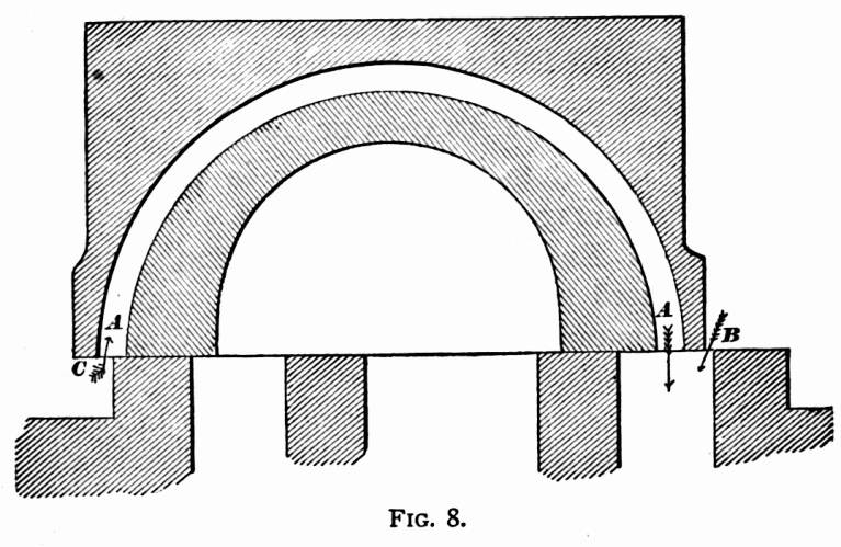 steam-passage, A,
A, cast above the exhaust cavity. The valve and seat are
so arranged, that, so soon as the outside edge of the valve begins
to uncover the steam-port at B, the supplementary passage
begins receiving steam at C; and this gives a double opening
for the admission of steam to the port when the travel is short.
As the travel of the valve is always short when an engine is running
at high speed, the advantage of this double opening is very great;
for it has the effect of admitting the steam promptly at the beginning
of the stroke, and maintaining a full pressure on the piston till
the point of cut-off. steam-passage, A,
A, cast above the exhaust cavity. The valve and seat are
so arranged, that, so soon as the outside edge of the valve begins
to uncover the steam-port at B, the supplementary passage
begins receiving steam at C; and this gives a double opening
for the admission of steam to the port when the travel is short.
As the travel of the valve is always short when an engine is running
at high speed, the advantage of this double opening is very great;
for it has the effect of admitting the steam promptly at the beginning
of the stroke, and maintaining a full pressure on the piston till
the point of cut-off.
ADVANTAGES OF THE ALLEN VALVE.
With an ordinary valve cutting off at six inches, and
having five inches eccentric throw, the port opening seldom exceeds
a inch. It is a hard matter
getting the full pressure of steam through such a small opening
in the instant given for admission. If an Allen valve is used
with that motion, the opening will be double, making w
inch, which makes an important difference. The practical
effect of a change of this kind is that an engine will take a
train along, cutting off at six inches with the Allen valve, when,
with the ordinary valve, the links would have to be dropped to
eight or nine inches. The valve can be designed to work on any
valve-seat, but the dimensions given in Fig. 8 are those that
have been found most satisfactory with our large passenger engines.
In designing an Allen valve for an old seat, it is sometimes advisable
to widen the steam-ports a quarter of an inch or more, by chamfering
off the outside edges that amount. Care must be taken to prevent
the valve from traveling so far as to put the supplementary port
over the exhaust-port, for that would allow live steam to pass
through. The proper dimensions can best be schemed out on paper
before making the required change on the seat.
In very carefully conducted experiments made on the Boston
and Albany Railroad, to compare the performance of the Allen valve
with an engine equipped with a common valve, it was found that
the Allen valve effected a fuel saving of seven per cent.
CASE WHERE THE ALLEN VALVE PROVED ITS
VALUE.
On one of the leading railroads in this country, an
engineer was running a locomotive on a fast train where it was
a hard matter making the card-time. A few minutes could be saved
by passing a water-station; but this was done at serious risk,
for the tender would nearly always be empty by the time the next
water station was reached. The master mechanic of the road determined
to equip this engine with the Allen valve: and, after the change
was made, there was no risk in passing the water-station; for
there always was a good margin of water in the tank when the next
watering-place was reached. The engine seemed to steam better,
because the work was done with less steam; and there was a decided
saving of fuel. The change made the engine smarter, and there
seems to be no limit to the speed it can make. This valve can
be applied to any locomotive with trifling expense. When an engine
is designed specially for the Allen valve, the steam ports and
bridges are usually made a little wider than for the ordinary
valve. The only real difficulty in adopting the valve is getting
the casting properly made, so that the supplementary port will
not be too rough for the passage of steam, and the thin shell
will be strong enough to stand the pressure.
INSIDE CLEARANCE.
For high-speed locomotives, where there is great necessity
for getting rid of the exhaust steam quickly, the valves are sometimes
cut away at the edges of the cavity, so that, when the valve is
placed in the middle of the seat, it does not entirely cover the
inside of either of the steam-ports. This is called inside clearance.
In many instances inside clearance has been adopted in an effort
to rectify mistakes made in designing the valve-motion, principally
to overcome defects caused by deficiency of valve-travel. The
fastest locomotives throughout the country do not require inside
clearance, because their valve-motion is so designed that it is
not necessary. Inside clearance induces premature release, and
diminishes the period of expansion. Consequently inside clearance
wastes steam, and ought to be avoided.
LEAD.
There are certain advantages gained in the working
of a locomotive, by having the valves set so that the steam-port
will be open a small distance for admission of steam, when the
piston is at the beginning of the stroke. This opening is called
lead. On the steam side of the valve the opening is called steam-lead:
on the exhaust side it is called exhaust-lead. Lead is generally
produced by advancing the eccentric on the shaft, its effect being
to accelerate every event of the valve's movement; viz., admission,
cut-off, release, and compression. In the most perfectly constructed
engines, there soon comes to be lost motion in the rod connections
and in the boxes. The effect of this lost motion is to delay the
movement of the valves; and, unless they are set with a lead opening,
the stroke of the piston would in some instances be commenced
before steam got into the cylinder. It is also found in practice,
that this lost motion would cause a pounding at each change in
the direction of the piston's travel, unless there is the necessary
cushion to bring the cranks smoothly over the centers. Without
cushion, the change of direction of the piston's travel is effected
by a series of jerks that are hard on the working-parts. So long
as the lead opening at the beginning of the stroke is not advanced
enough to produce injurious counter pressure upon the piston,
it improves the working of the engine by causing a prompt opening
for steam admission at the beginning of the stroke. This is the
time that a full steam-pressure is wanted in the cylinder, if
economical working be a consideration. A judiciously arranged
lead opening is therefore an advantage; since it increases the
port opening at the proper time for admitting steam, tending to
give nearly boiler pressure in the cylinder at the beginning of
the stroke. With the shifting link-motion, the amount of lead
opening increases as the links are hooked back towards the center
notch; the magnitude of the increase, in most cases, being in
direct proportion to the shortness of the eccentric-rods. A common
lead opening in full gear with the shifting link is z
inch, which often increases to a
inch in the center notch. The tendency of wear and lost motion
is to neutralize the lead, so that, when a locomotive motion gets
worn, increasing the lead will generally improve the working of
the engine.
OPERATION OF THE STEAM IN THE CYLINDERS.
As the work performed by a steam-engine is in direct
proportion to the pressure exerted by the steam on the side of
the piston which is pulling or pushing on the crank-pin, it is
important that the steam should press only on one side of the
piston at once. Hence, good engines have the valves operated so
that, by the time a stroke is completed, the steam, which was
pushing the piston, shall escape, and not obstruct the piston
during the return stroke, and so neutralize the steam pressing
upon the other side. When an engine is working properly, the steam
is admitted alternately to each side of the piston; and its work
is done against a pressure on the other side not much higher than
that of the atmosphere.
BACK PRESSURE IN THE CYLINDERS.
When, from any cause, the steam is not permitted to
escape promptly and freely from the cylinder at the end of the
piston stroke, a pressure higher than that of the atmosphere remains
in the cylinder, obstructing the piston during the return stroke,
and causing what is known as back pressure. There is seldom trouble
for want of sufficient opening to admit steam to the cylinders,
for the pressure is so great that the steam rushes in through
a very limited space; but, when the steam has expanded two or
three times, its pressure is comparatively weak, and needs a wide
opening to get out in the short time allowed. This is one reason
why the exhaust-port is made larger than the admission-ports.
Nearly all engines with short ports suffer more or less from back
pressure, but the most fruitful cause of loss of power through
this source is the use of extremely contracted exhaust nozzles.
Were it not for the necessity of making a strong artificial draught
in the smokestack, so that an intense heat shall be created in
the fire-box, quite a saving of power, now lost by back pressure,
would be effected by having the exhaust opening as large as the
exhaust-pipe. This not being practicable with locomotives, engineers
should endeavor to have their nozzles as large as possible consistent
with steam-making.
Engines with very limited eccentric throw will often cause
back pressure when hooked up, through the valve not opening the
port wide enough for free exhaust.
Locomotives suffering from excessive back pressure are nearly
always logy. The engine can not be urged into more than moderate
speed under any circumstances; and all work is done at the expense
of lavish waste of fuel, for a serious percentage of the steam-pressure
on the right side of the piston is lost by pressure on the wrong
side. It is like the useless labor a man has to do turning a grindstone
with one crank, while a boy is holding back on the other side.
The weight of obstruction done by the boy must be subtracted from
the power exerted by the man to find the net useful energy exerted
in turning the grindstone. In the same way, every pound of back
pressure on a piston takes away a pound of useful work done by
the steam on the other side.
EFFECT OF TOO MUCH INSIDE LAP.
Engines that have much inside lap to the valves are
likely to suffer from back pressure when high speed is attempted.
The inside lap delays the release of the steam; and, where the
piston's velocity is high, the steam does not escape from the
cylinder in time to prevent back pressure.
RUNNING INTO A HILL.
Most of engineers are familiar with the tendency of
some engines to "run into a hill." That is, so soon
as a hill is struck, they suddenly slow down till a certain speed
is reached, when they will keep going. This is generally produced
by back pressure, its obstructing effect being reduced when the
engine is moving slow.
COMPRESSION.
The necessity which requires lap to be put on a slide-valve
to produce an early cut-off, in its turn causes compression, by
the valve passing over the steam-port, and closing it entirely
for a limited period towards the end of the return stroke. As
the cylinder contains some steam which did not pass out while
the exhaust-port was open, this is now squeezed into a diminishing
space by the advancing piston. In cases where too much steam was
left in the cylinders through contracted nozzles or other causes,
or where, through mistaken designing of the valve-motion, the
port is closed during a protracted period, the steam in the cylinder
gets compressed above boiler tension, and loss of useful effect
is the result. Under proper limits, the closing of the port before
the end of the stroke, and the consequent compression of the steam
remaining in the cylinder, have a useful effect on the working
of the engine by providing an elastic cushion, which absorbs the
momentum of the piston and its connections, leading the crank
smoothly over the center. Where it can be so arranged, the amount
of compression desirable for any engine is the degree that, along
with the lead, will raise the pressure of the cylinder up to that
of the boiler at the beginning of the stroke. When this can be
regulated, the compression performs desirable service by cushioning
the working-parts, thereby preventing pounding, and by filling
up the clearance space and steam passages, by that means saving
live steam. Compression probably does some economical service
by reheating the cylinder, which has a tendency to get cooled
down during the period of release, and by re-evaporating the water,
which forms by condensation of steam in the cool cylinder.
Engines that are running fast require more cushioning than
those that run slow, or at moderate speeds. The link-motion, by
its peculiarity of hastening compression when the links are hooked
up, tends to make compression a useful service in fast running.
DEFINITION OF AN ECCENTRIC.
The reciprocating motion which causes the valves to
open and close the steam-ports at the proper periods, is, with
most locomotives, imparted from eccentrics fastened upon the driving-axle.
An eccentric is a circular plate, or disk, which is secured to
the axle in such a position that it will turn round on an axis
which is not in the center of the disk. The distance from the
center of the disk to the point round which it revolves is called
its eccentricity, and is half the throw of the eccentric. Thus,
if the throw of an eccentric requires to be 5 inches, the distance
between the center of the driving-axle and the center of the eccentric
will be 22, inches. The movement
of an eccentric is the same as that of a crank of the same stroke,
and the eccentric is preferred merely because it is more convenient
for the purposes to which it is applied than a crank would be.
EARLY APPLICATION OF THE ECCENTRIC.
On the early forms of locomotives, a single eccentric
was used to operate the valve for forward and back motion. The
eccentric was made with a half circular slot, on which it could
be turned to the position needed for forward or back motion. It
was held in the required position by a stop-stud fastened on the
axle. Several forms of movable eccentrics were invented, and received
considerable application during the first decade of railroad operating;
but the best of them provided an extremely defective reversing
motion. The first engineer to apply two fixed eccentrics as a
reversible gear was William T. James of New York, who made a steam
carriage in 1829, and worked the engine with four eccentrics,—two
for each side. The eccentrics were connected with a link, but
the merits of that form of connection were not then recognized
here; for it was not applied to locomotives till it became popular
in England, and was re-introduced to this country by Rogers. The
advantage of the double fixed eccentrics seemed, however, to be
recognized from the time James used them; for the plan was adopted
by our first locomotive builders. The first locomotive built by
Long, who started in 1833 what was afterwards known as the Norris
Locomotive Works, Philadelphia, had four fixed eccentrics.
RELATIVE MOTION OF PISTON AND CRANK,
SLIDE-VALVE, AND ECCENTRICS.
When a locomotive is running, the wheels turn with
something near a uniform speed; but any part which receives a
reciprocating motion from a crank or eccentric travels at an irregular
velocity. Fig. 9 shows the relative motion of the crank-pin and
piston during a half revolution. The points in the path of the
crank-pin marked A, 1, 2, B, 3, 4, C, are
at equal distances apart. The vertical lines run from them to
the points a, b, c, d, e, represent the position of the
piston in relation to the position of the crank-pin. That is,
while the crank-pin traverses the half-circle, A B C, to
make a half revolution, the piston, guided by the
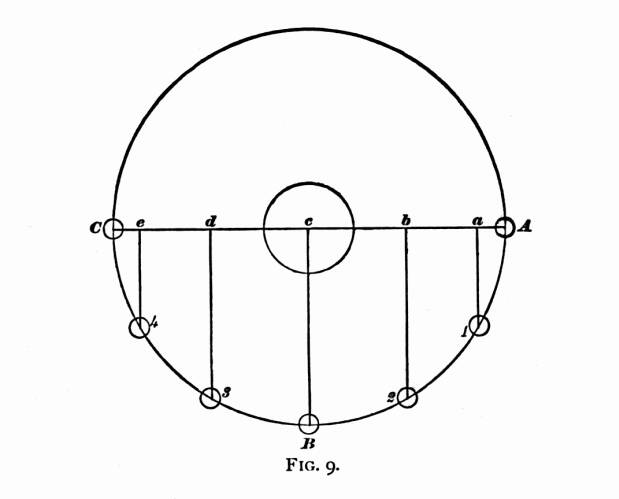
cross-head, travels a distance within the cylinder equal to
the straight line A C. The crank-pin travels at nearly
uniform speed during the whole of its revolution, but the piston
travels with an irregular motion. Thus, while the crank-pin travels
from A to 1, the piston travels a distance equal to the
space between A and a. By the space between the
lines, it will be seen that the piston travels slowly at the beginning
of the stroke, gets faster as it moves along, reaches its highest
velocity about half stroke, then slows down towards the end till
it stops, and is ready for the return stroke.
ATTEMPTS TO ABOLISH THE CRANK.
Certain mechanics and inventors have been terribly
harassed over this irregular motion of the piston, and numerous
devices have been produced for the purpose of securing a uniform
motion to the power transmitted. These inventions have usually
taken the shape of rotary engines. Probably the fault these people
find with the reciprocating engine is one of its greatest merits,
for the piston stopping at the end of each stroke permits an element
of time for the steam to get in and out of the cylinder.
VALVE MOVEMENT.
The valve travels in a manner similar to the piston;
although its stroke is much shorter, and its slow movement is
towards the limit of travel. The small circle in the figure shows
the orbit of the eccentric's center, and the valve-travel is equal
to the rectilinear line across the circle. If the valve opened
the steam-ports at the outside of its travel, the slow movement
at that point would be an objection, since the operation of opening
would be slow: but the valve opens the ports towards the middle
of its travel, when its velocity is greatest; and, the nearer
to the mid travel the act of opening is done, the more promptly
it will be performed. This has a good deal to do with making an
engine "smart" in getting away from a station.
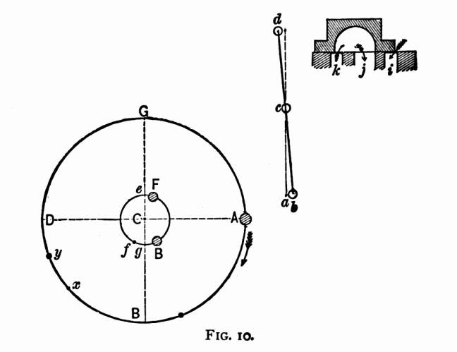
EFFECT OF LAP ON THE ECCENTRIC'S POSITION.
With the short valve without lap used on the earliest
forms of locomotives, the eccentric was set at right angles to
the crank or "square" on the dotted line e, Fig.
10. The least movement of the eccentric from its middle position
had the effect of opening the steam-ports. One advantage about
an eccentric set in this position, was that it opened and closed
the ports when moving the valve at its greatest velocity. Lengthening
the valve-face by providing lap entails a change in the location
of the eccentric; for, were it left in the right-angle position,
the steam-port would remain covered till the eccentric had moved
the valve a distance equal to the extent of the lap on one end,
and the piston would begin its stroke without steam.
ANGULAR ADVANCE OF ECCENTRICS.
The change made on the eccentric location is to advance
it from e to F, being a horizontal distance equal
to the extent of lap and lead, and known as the angular advance
of the eccentric. The centers F and B represent
the full part, or "belly," of the forward and back eccentrics
in the position they should occupy, where a rocker is employed,
when the piston is at the beginning of the backward stroke. It
will be perceived that the eccentrics both incline towards the
crank-pin, and the eccentric which is controlling the valve follows
the crank-pin. Thus, when the engine is running forward, F
follows the crank: when she is backing, B follows.
It is a good plan for an engineer to make himself familiar
with the proper position of the eccentrics in relation to the
crank, for the knowledge is likely to save time and trouble when
any thing goes wrong with the valve-motion. With this knowledge
properly digested, a minute's inspection is always sufficient
to decide whether or not any thing is wrong with the eccentrics.
ANGULARITY OF CONNECTING ROD.
In following out the relative motion of the piston
and crank, we discover a disturbing factor in what is called the
angularity of the connecting rod, which has a curiously distorting
effect on the harmony of the motion. When the piston stands exactly
in the mid-travel point, the true length of the main rod will
be measured from the center of the wrist-pin to the center of
the driving-axle. If a tram of this length be extended between
these points, this will be found correct, as every machinist accustomed
to working on rods knows. Now, if the back end of the tram should
be raised or lowered towards the points where the center of the
crank-pin must be when the crank stands on the top or bottom quarter,
it will be found that the tram point will not reach the crank-pin
center, but will fall short a distance in proportion to the length
of the main rod. The dotted lines a' and b' in Fig.
11 show how far a rod 72 times
the length of the crank falls short. A shorter rod will magnify
this obliquity, while a longer rod will reduce it.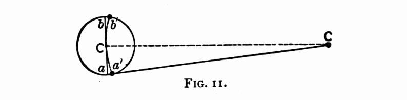
EFFECT ON THE VALVE-MOTION OF CONNECTING-ROD
ANGULARITY.
As the opening and closing of the steam-ports by the
valves are regulated by the eccentrics, which are subject to the
same motion as the crank, following it at an unvarying distance,
it is evident that their tendency will be to admit and cut off
steam at a certain position of the crank's movement. If the motion
is planned to cut off at half stroke, it will be apparent, that,
in the backward stroke, the piston will be past its mid travel
before the crank-pin reaches the quarter, so that end of the cylinder
will receive steam during more than half the stroke. On the forward
stroke of the piston, however, the crank-pin will reach the quarter
before the piston has attained half travel; the consequence being,
that in this case steam is cut off too early. The disturbing effect
of the angularity of the connecting rod on the steam distribution
thus tends to make the cut-off later in the backward stroke than
in the forward stroke, resulting in giving the forward end of
the cylinder more steam than what is admitted in the back end.
The link-motion provides a convenient means of correcting the
inequality of valve opening due to the connecting-rod angularity,
the details of which will be explained farther on.
AIDS TO THE STUDY OF VALVE-MOTION.
An engineer or machinist who wishes to study out this
peculiarity of connecting-rod angularity, will find that the use
of a tram or long dividers will help him to comprehend it better
than any letter-type description. All through the study of the
valve-motion, there are numerous difficult problems encountered.
The use of a good model will be found an invaluable aid to the
study of the valve-motion, and every division of engineers or
firemen should make a combined effort to furnish their meeting-room
with a model of a locomotive valve-motion. In no way can the spare
time of the men connected with locomotive running be better employed
than in the wide range for study presented by a well devised model.
Great aid can be obtained in the study of the valve-motion from
good books devoted to the subject, and they will impart more information
than can be obtained by mere contact with the locomotive. The
valve and its movements are surrounded with so many complicated
influences, that an intelligent man may work for years about a
locomotive doing valve setting occasionally, and other gang boss
work, yet, unless he studies the valve-motion by the aid of the
drawing board, or by models, which admit of changing sizes and
dimensions, he may know less about the cause of certain movements
than the bright lad who has been a couple of years in the drawing-office.
The man who thinks he can study the valve-motion, and understand
its philosophy, by merely running the engine, deceives himself.
The engineer who never looks at a book or a paper in search of
information about his engine, knows very little about any thing
not visible to the eye. Yet many men of this stamp, by looking
wise, and by exercising a judicious use of silence, pass among
their fellows as remarkably profound. But let a fireman, in quest
of locomotive knowledge, put a question to such a man, and he
is immediately silenced with a "You ought to know better"
answer.
Where the use of a model can not be obtained, any one beginning
the study of the valve-motion can assist himself by making a cross
section of the valve and its seat, similar to those published,
on a strip of thin wood or thick paper. By slipping the valve
on the seat, its position at different parts of the stroke can
be comprehended more clearly than by a mere description. With
a pair of dividers to represent the motion of the eccentric, and
strips of wood to act as eccentric, and valve rod and rocker,
and some tacks to fasten them together, a helpful model can be
improvised on a table or board. By the time a student gets a rig
of this kind going, he will see his way to contrive other methods
of self-help.
EVENTS OF THE PISTON STROKE.
By the aid of Fig. 10, we will trace the relative movements
of the crank and eccentric connections. For the sake of simplicity,
the eccentric is represented as connecting directly with the rocker-arm.
The crank-pin being at the point A, or the forward center,
the piston must be in the front of the cylinder, or at the beginning
of the backward stroke. Owing to the angular advance already referred
to, the eccentric center is at F; and, being a certain
distance ahead of the middle position, it has pushed the lower
arm of the rocker from a to b, drawing back the
top arm, which, in its turn, has moved the valve so that it is
just beginning to admit steam at the forward port, i. As
the crank-pin goes round, the eccentric follows it, opening the
steam-port wider till the eccentric reaches the point of its travel
nearest A, the limit of the throw. When the eccentric is
at this point of its throw, the valve must be at the outside of
its travel; and therefore the steam-port is wide open. By this
time the crank-pin is getting close up towards the quarter. After
passing this point, the forward eccentric begins to draw the bottom
rocker-pin towards the axle, and to push the valve ahead, this
being the point where the valve changes its direction of motion
just as the piston returns when the crank-pin passes the center.
When F reaches the point B, the valve is in the
same position it occupied at the beginning of the stroke; but,
as it is traveling in the opposite direction, a very small movement
more closes the port, cutting off steam. When this happens, the
crank-pin has reached the point x. When F gets to
g, it is on the central point of its throw; so the valve
must then be on the middle point of its travel, with the exhaust
cavity just covering the outside edges of the bridges, the forward
edge being ready to put the steam-port, i, in communication
with the exhaust cavity. This releases the steam from the forward
end of the cylinder; and at the same moment the inside edge of
the valve covers the back port, k, causing the piston-head
to compress any steam left in the back part of the cylinder. When
the piston reaches the beginning of the forward stroke, the eccentric
F has got to the point f, and the valve is beginning
to admit steam for the return stroke, the events of which are
similar to those described.
In actual practice, the steam distribution is a little different
from the manner that has been followed; for the link-motion provides
the means of equalizing the cutoff, making it uniform for both
strokes. This changes the events of the stroke a little; but the
student who engraves in his mind the movements as they are represented
in the diagram, will not be far astray.
WHAT HAPPENS INSIDE THE CYLINDERS WHEN
AN ENGINE IS REVERSED.
Many men who have a fair understanding of the action
of steam in an engine's cylinders during ordinary working, have
no idea of the operations performed in the cylinders when a locomotive
is running in reverse motion. All men who have had any thing to
do with train service, know, that, when an engine is reversed,
the action works to stop the train, even if the locomotive should
have no steam on the boiler; but just in what way this result
comes round they can not clearly perceive. In hopes of throwing
light upon this subject for those who have not studied it out,
we will follow the events of a stroke in reversed motion, as we
did in the ordinary working.
EVENTS OF THE STROKE IN REVERSED MOTION.
Supposing an engine to be running ahead, and the necessity
arises for stopping suddenly, and the reverse-lever is pulled
into the back notch. When the crank-pin is on the forward center,
and therefore the piston at the forward end of the cylinder, about
to begin its backward stroke, the valve has the forward port open
a distance equal to the amount of lead, as in Fig. 10. But, as
the back-up eccentric has control of the valve., the latter is
being pushed forward; and it closes the forward port just as the
piston begins to move back. This shuts off all communication with
the forward end of the cylinder; and the receding piston creates
a vacuum behind it, just as a pump-plunger does under similar
circumstances. At this time the back end of the cylinder is open
to the exhaust, and the piston pushes out the air freely to the
atmosphere. By the time the piston travels about two inches, the
valve gets to its middle position; and, immediately after passing
that point, it opens the forward end of the cylinder to the exhaust,
and closes the back port. When this event happens, the vacuum
in the forward end of the cylinder gets filled with hot gases,
that rush in from the smoke-box; and the receding piston keeps
drawing air into the cylinder in this way during the remainder
of the stroke, and air from that quarter seldom gets in without
bringing a sprinkling of cinders. The back steam-port is closed
only during about two inches of the stroke, while the lap of the
valve is traveling over it. About the time the piston reaches
four inches of its travel, the back steam-port is open to the
steam-chest, and the piston forces the air through the steam-pipes
into the boiler during the remainder of the stroke. The forward
stroke is merely a repetition of the backward stroke described.
When it is necessary to reverse a locomotive, it is a better
plan to hook the lever clear back than to have it a notch or two
past the center, as some men persist in doing, under the mistaken
belief that they are in some way saving their engine from harsh
usage. When the link is reversed full, the cylinders are merely
turned into air-pumps. When the links are put near the center,
the travel of the valve is reduced; and the periods when the piston
is creating a vacuum in one end of the cylinder, and compressing
the air in the other, are prolonged. The result is, that, when
the exhaust is opened in the first case, the gases rush in violently
from the smoke-box, carrying a heavy load of cinders: in the other
case, the piston compresses the air in the cylinder so high that
it jerks the valve away from its seat in trying to find outlet.
This causes the clattering noise in the steam-chest, so well known
in cases where engines are run without steam while the reverse-lever
is near the center.
A locomotive with the piston-packing in bad order will not
hold well running in reverse-motion. Some kinds of piston-packing
do not seem to act properly when the engine is reversed, especially
at low speed. Where a valve has much inside lap, there will be
a vacuum in one end of the cylinder, and compressed air in the
other end. With piston-packing that requires pressure to expand
it, the void at one end of the cylinder may neutralize the pressure
at the other by drawing the air through the piston. This would
be most liable to happen where the lever was kept near the center.
PURPOSE OF RELIEF-VALVE ON DRY PIPE.
Should the throttle-valve close so tight that the compressed
air from the cylinders can not pass into the boiler, there is
danger of bursting the steam-chest or some part of the, steam-pipes.
The compressed air will lift most of the throttle-valves far enough
to prevent any great danger from this source. In some engines
a relief-valve is secured in the dry pipe, which provides a passage
for this compressed air. When the cylinder-cocks of an engine
are opened when the motion is reversed, they form an outlet to
the compressed air, and also admit air to the sucking end without
letting the piston draw air so freely through the nozzles. Many
cylinder-cocks are now made so that they will open automatically
to permit the piston to draw air through them. The reversed engine
will stop nearly as well with the cylinder-cocks opened as when
they are closed, and it is much more easily handled with the cocks
opened. Where the cocks are kept closed, the rush of hot air from
the smoke-box laps every trace of oil from the valve-seat, and
a heavy pressure — frequently above that of the boiler —
is present in the steam-chest. When the engine stops under these
circumstances, its tendency is to fly back; and an engineer has
some difficulty in controlling it with the reverse-lever till
a few turns empty the chest and pipes.
USING REVERSE-MOTION AS A BRAKE.
Numerous attempts have been made to utilize the reversed
engine as a brake for stopping the train, and even by this means
to save some of the power lost in stopping. Chatelier, a French
engineer, experimented for many years on this mechanical problem.
He injected a jet of water into the exhaust-pipe, which supplied
low-tension steam to the cylinder, instead of hot gas or air coming
through the smoke-box. This was pumped back into the boiler on
the return stroke. Thus the act of stopping a train was used to
compress a quantity of steam, converting the work of stopping
into heat, which was forced into the boiler and retained to aid
in getting the train into speed again. Modifications of this idea
produce the car-starters that pass so frequently through our Patent
Office.
As a means of conserving mechanical energy, the Chatelier brake
was not a success; but, in the absence of better power brakes,
it met with some applications in Europe. Some of our mountain
railroads use it, under the name of the water-brake, as an auxiliary
to the automatic brake.
Table of Contents
| Contents Page
|