|
CHAPTER XIX.
SETTING THE VALVES.
THE MEN WHO LEARN VALVE-SETTING.
MOST of intelligent machinists engaged on engine work, make it
an object of ambition to learn to set valves; and the operation
is mastered as soon as the opportunity offers. It has been a practice
in numerous shops for those who have the work of valve-setting
to do, to invest the operation with fictitious mystery, to patiently
disseminate the belief that valve-setting is an exceedingly difficult
matter. Cases sometimes arise where the squaring of an engine's
valves is really an arduous task, requiring intimate familiarity
with delicate methods of adjustment; but valve-setting, as it
is usually practiced in building establishments, in repairing-shops,
and in round-houses, is merely a matter of plain measurement.
A man may be a first-class engineer without knowing how to
set valves, and familiar acquaintance with the operation will
not increase his ability in managing his engine when merely getting
a train over the road on time is the consideration; but the method
of valve setting is so closely associated with an intelligent
appreciation of the valve-motion's philosophy, that most of engineers
who take an extended interest in their business, wish to acquire
the knowledge of how the valves are set.
BEST WAY TO LEARN VALVE-SETTING.
The best way to learn valve-setting is by taking part
in the work. Whatever can be said in books on a subject of this
kind, provides but an indifferent substitute for going through
the actual operations. But a man's ambition to learn may exceed
his opportunities; so, for those who can not get a gang boss to
direct them into the art of valve-setting, this description will
be made as plain as possible.
When an engine's valve-motion is designed, the sizes of the
different parts are arranged; and, if this business is done by
a competent engineer, there will only be trifling changes necessary
in valve-setting.
PRELIMINARY OPERATIONS.
Let us suppose the engine to be an ordinary eight wheel
locomotive, with cylinders 17 X 24 inches. Let us assume that
the top and bottom rocker-arms are straight, of equal length,
and that the eccentric-rods are connected to the link so as to
be opposite the block in full gear. This will make the extreme
travel of valve equal the eccentric's throw. We will now look
round to see that every thing connected with the motion is ready
for valve-setting.
First, it is necessary to see that the wedges are properly
set up to hold the driving-boxes in about the same position they
will occupy when the engine is at work.
CONNECTING ECCENTRIC-RODS TO LINK.
In looking over the motion, it is well to note that
the eccentric-rods are properly connected, — the forward
eccentric-rod with the top, the backward eccentric-rod with the
bottom, of the link. When the crank-pin is on the forward center,
the eccentrics 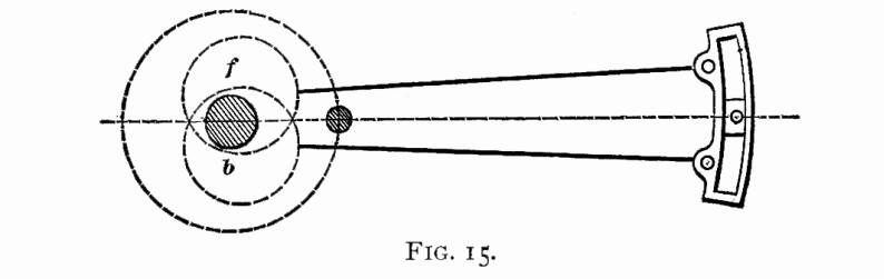 will
occupy the position they appear in, in Fig. 15, where the rods
are open, and nearly horizontal. The full parts of both eccentrics
are advanced towards the crank-pin, so that the centers of the
eccentrics are advanced from a perpendicular line drawn through
center of axle, a horizontal distance equal to the lap and lead.
When the crank-pin is on the back center, the will
occupy the position they appear in, in Fig. 15, where the rods
are open, and nearly horizontal. The full parts of both eccentrics
are advanced towards the crank-pin, so that the centers of the
eccentrics are advanced from a perpendicular line drawn through
center of axle, a horizontal distance equal to the lap and lead.
When the crank-pin is on the back center, the 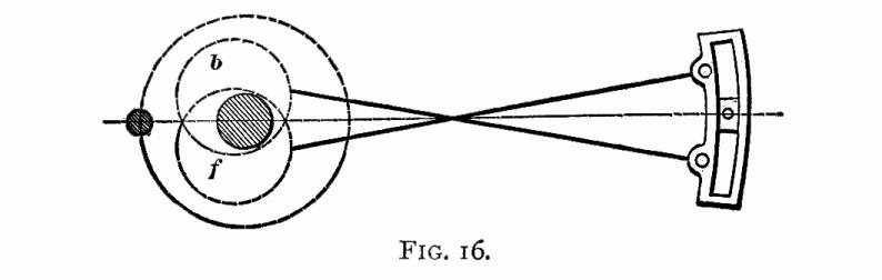 eccentric centers will be behind the
axle, and the rods will be crossed as they are seen in Fig. 16.
The reason why the rods must be crossed when the crank is in this
position, is, that the forward eccentric center is below the axle,
and the backward eccentric center is above, As the forward eccentric-rod
maintains its connection with the top of the link, and the backward
eccentric-rod is at the opposite end, crossing of the rods is
inevitable. This fact is worth imprinting on the memory, for I
have known of several cases where men got the rods up wrong by
putting them open when the engine stood with the crank on the
back center. eccentric centers will be behind the
axle, and the rods will be crossed as they are seen in Fig. 16.
The reason why the rods must be crossed when the crank is in this
position, is, that the forward eccentric center is below the axle,
and the backward eccentric center is above, As the forward eccentric-rod
maintains its connection with the top of the link, and the backward
eccentric-rod is at the opposite end, crossing of the rods is
inevitable. This fact is worth imprinting on the memory, for I
have known of several cases where men got the rods up wrong by
putting them open when the engine stood with the crank on the
back center.
MARKING THE VALVE-STEM.
In ordinary practice, valves are set with the steam-chest
cover down, and the position of the valve on the seat is identified
by marks on the valve-stem. Before the cover is put down, the
valve is placed as in Fig. 17, just beginning to open the forward
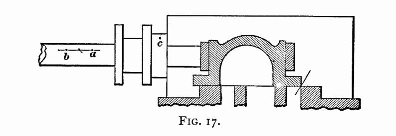 steam-port; a
thin piece of tin being generally used to gauge the opening When
the valve stands in this position, a tram is extended from a center
punch-mark c, on the stuffing-box, straight along the valve-stem
as far as it will reach; and the point, here located at a,
is marked. The valve is then moved forward till it begins to uncover
the back port, when another measurement is made with the tram,
which locates the point b on the valve-stem. Whatever position
the valve may stand on, it may now be identified by the tram,
When the tram cuts the space half way between a and b,
the valve stands in the middle of the seat. steam-port; a
thin piece of tin being generally used to gauge the opening When
the valve stands in this position, a tram is extended from a center
punch-mark c, on the stuffing-box, straight along the valve-stem
as far as it will reach; and the point, here located at a,
is marked. The valve is then moved forward till it begins to uncover
the back port, when another measurement is made with the tram,
which locates the point b on the valve-stem. Whatever position
the valve may stand on, it may now be identified by the tram,
When the tram cuts the space half way between a and b,
the valve stands in the middle of the seat.
Some machinists do not believe in tramming from the stuffing-box,
as the point is liable to be moved in tightening down the steam-chest
cover. These generally measure from a point on the cylinder casting,
but that practice has its drawbacks.
LENGTH OF THE VALVE-ROD.
To prove the correct length of the valve-rod, the rocker-arm
is set at right angles to the valve-seat, which is its middle
position. The valve must now stand on the middle of the seat,
which will be indicated by the tram point reaching the dividing
point between a and b. Should the valve not be right
when the rocker is in its middle position, the rod must be altered
to put it right.
ACCURACY ESSENTIAL IN LOCATING THE DEAD
CENTER POINTS.
Before proceeding to set the valves, a machinist can
not be too careful in locating the exact dead centers. Some men
conclude, because there is little motion to the cross-head close
to the end of the stroke, that a slight movement of the wheel
to one side or the other is of little consequence, and makes no
perceptible difference in the relative positions of piston and
valve. This is a serious mistake; for, although the piston is
moving slowly, the eccentric is proceeding at its ordinary speed,
and the valve is moving fast. The loose, quick methods of finding
dead centers followed occasionally are not conducive to exactness,
and nothing but accuracy is permissible in valve-setting.
FINDING THE DEAD CENTERS.
The best way of finding the true center is by moving
the cross-head a measured distance round its extreme travel, recording
the extent of movement on the driving-wheel tire, whose motion
is uniform; then bisecting the distance between the marks on the
tire, when the dividing line will indicate the true center.
Thus: Turn the wheels forward till the cross-head reaches within
one-half inch of its extreme travel, as shown in Fig. 18. From
a 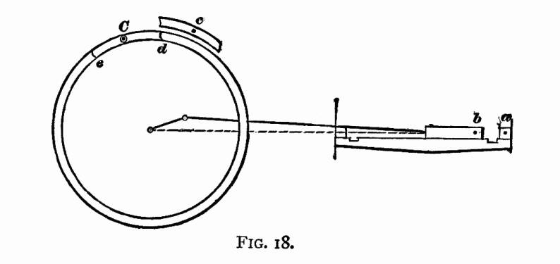 point a
on the guide-block, extend a tram on the cross-head, and mark
the extreme point reached b. Put a center punch-mark c
on the wheel-cover, or other convenient fixed point, and from
it extend a tram on the edge of the tire, and scratch an arc d.
Now, with tram in hand, watch the cross-head, and have the wheels
moved forward slowly. When the cross-head passes the center, and
moves back till the tram extending from a will reach the point
b, stop the motion. Again tram from the wheel-cover point,
and describe a second arc on the tire, which will be at e,
now moved to the position which d occupied when the previous
measurement was taken. With a pair of dividers bisect the distance
between d and e. Mark the dividing point C with
a center punch, and put a chalk ring round it. When the wheel
stands so that the tram will extend from c to C,
the engine will be on the forward dead center. point a
on the guide-block, extend a tram on the cross-head, and mark
the extreme point reached b. Put a center punch-mark c
on the wheel-cover, or other convenient fixed point, and from
it extend a tram on the edge of the tire, and scratch an arc d.
Now, with tram in hand, watch the cross-head, and have the wheels
moved forward slowly. When the cross-head passes the center, and
moves back till the tram extending from a will reach the point
b, stop the motion. Again tram from the wheel-cover point,
and describe a second arc on the tire, which will be at e,
now moved to the position which d occupied when the previous
measurement was taken. With a pair of dividers bisect the distance
between d and e. Mark the dividing point C with
a center punch, and put a chalk ring round it. When the wheel
stands so that the tram will extend from c to C,
the engine will be on the forward dead center.
All the other centers must be found by a similar process.
TURNING WHEELS AND MOVING ECCENTRICS.
When a measurement is going to be made for fore gear,
the wheels must be turned forward; and, when it is for the back
gear, they must be turned backward. Enough movement of the wheel
must be given to take up the lost motion every time the direction
of movement is changed. In moving an eccentric, it should also
be turned far enough in the opposite direction to take up the
lost motion.
SETTING BY THE LEAD OPENING.
Put the reverse-lever in the full forward notch, and
place the engine on the forward center. If the lead opening in
full gear is to be z inch,
advance the forward eccentric till the point a (Fig. 17)
on the valve-stem is that distance away from the tram point. Throw
the reverse-lever into the full backward notch, turn the wheels
forward enough to take up the lost motion, then turn them back
to the forward center. Move the backward eccentric (if it needs
moving) till the tram, extended on the valve-stem, strikes the
same point that it reached for the forward motion. It will be
noted here, that the valve occupies the same position for fore
and back gear when the engine is on the center. Put the reverse-lever
in the forward notch again, and turn the wheels ahead till the
back center point is reached. Now tram the valve-stem again, and,
if the lead opening be the same for both gears as it was on the
forward center, that part of the setting is right. It is a good
plan to go over the points a second time to prove their corectness.
But it is not likely that the lead opening at the back end will
be right on the first trial. Instead of having the correct lead,
the valve will probably lap over the port, being what workmen
call "blind," or it will have too much lead. Let us
assume that our valve is z inch
blind. This indicates that the eccentric-rod is too long. We shorten
the rod till the valve is at the opening point, and, on turning
the engine to the forward center again, we will find that the
valve there has lost its lead. But our change has adjusted the
valve movement, so that on each center the valve is just beginning
to open the steam-port. Advancing the eccentric to give one end
z inch lead will now have the
same effect upon the other end; and, assuming that the back motion
has been subjected to similar treatment with a like result, the
lead opening on that side is right. This process must now be repeated
with the other side of the engine.
ASCERTAINING THE POINT OF CUT-OFF.
The lead openings being properly arranged, we will
proceed to examine how the valves cut off the steam; for it is
important that about the same supply of steam should be furnished
to each cylinder and to each end of the cylinders. The angularity
of the connecting rod tends to give a greater supply of steam
to the forward than to the back end of the cylinder; but this
inequality is, as has already been explained, usually rectified
by locating the hanger-stud a certain distance back of the link
arc.
To prove the cut-off, we will try the full gear first. Put
the reverse-lever in the full forward notch, starting from the
forward center, and turn the wheels ahead. The motion of our engine
has been designed so that the cut-off in full gear shall happen
at 18 inches of the stroke. With tram in hand, watch the movement
of the valve as indicated by the stem marks. As the piston moves
away from the forward end of the cylinder, the valve will keep
opening till nearly half stroke is reached, when it will begin
to return, slowly at first, but with increasing velocity as the
point of cutoff is reached. When the point a, Fig. 17,
gets so that it will be reached by the tram extended from c,
the motion must be stopped; as that indicates the point of cutoff.
Now measure on the guide how far the cross-head has traveled from
the beginning of the stroke, and mark it down with chalk. Then
turn the wheels in the same direction past the back center, and
obtain the cut-off for the forward stroke in the same manner.
The cutoff for the other cylinder will be found in precisely the
method described.
In addition to trying the cut-off in full gear, it is usually
tested at half stroke and at 6 inches, or with the reverse-lever
in the notches nearest to these points. Some men begin at the
first notch, and follow the point of cut-off in every notch till
the center is reached, and do the same for back gear.
ADJUSTMENT OF CUT-OFF.
From various causes, it often happens that the cut-off
is unequal in the two strokes, or one cylinder may be getting
more steam than the other. Suppose, that, on one side of the engine
the valve is cutting off at 182
inches in forward gear, while at the other side it is cutting
off at 172 inches of the stroke.
The most ready way to adjust that inequality is by shortening
one link-hanger and lengthening the other till a mean is struck.
Where the discrepancy is smaller, it is adjusted by lengthening
the hanger at the short side.
A harder inequality to adjust is where the valve cuts off earlier
for one end of the cylinder than for the other. In new work this
is readily overcome by the saddle-stud, but such a change is seldom
admissible in old work. When the points of cut-off have been noted
down, it will frequently happen, that, instead of both ends cutting
off at 18 inches, one end will show the cut at 17 inches, while
the other goes to 19 inches. This indicates something wrong, and
demands a search for the origin of the unequal motion. First ascertain
if the rocker-arm is not sprung. If that is all right, examine
the link, which is probably sprung out of its true radius. To
straighten the rocker-arm is an easy matter, but not so with case-hardened
links; although some men are very successful in springing them
back. Where it is impracticable to remedy an unequal cut-off by
correcting the origin of the defect, several plans may be resorted
to for obtaining the required adjustment. One of the most common
resorts is to equalize the forward motion by throwing out the
back motion. Putting the rocker-arm away from its vertical position
when the valve is in the middle of the seat, by shortening or
lengthening the valve-rod, provides a means of adjustment. Sometimes
the equality of lead opening is sacrificed to obtain equality
of cut-off. The changes necessary to obtain adjustment of a distorted
motion can only be successfully arranged by one who has experience
in valve-setting or in valve-motion designing.
In many shops the cut-off is adjusted for the point where the
engine does most of the work,—say at 6 inches. Other master
mechanics direct the equalization to be made for half stroke,
while some take the mean between the half stroke and the ordinary
working notch.
The final adjustments in valve-setting ought to be made when
the engine is hot.
Table of Contents
| Contents Page
|