|
CHAPTER XXII.
THE EAMES VACUUM BRAKE.
OPERATION OF THE BRAKE.
THE Vacuum Brake, as the name implies, is operated
by means of a vacuum which is formed in the connections that act
the part of the cylinder in the air-brake. With an air-brake,
compressed air is made to do the work of applying the brakes by
moving a piston to which the brake-lever is attached, the air
being carried throughout the train by means of iron pipes and
rubber hose: with the vacuum brake the work is done in a similar
way with similar connections; but, instead of compressed air being
forced inside the pipes and apparatus, all the air is exhausted
out, and the natural pressure of the atmosphere is made to do
the work.
THE DIAPHRAGM.
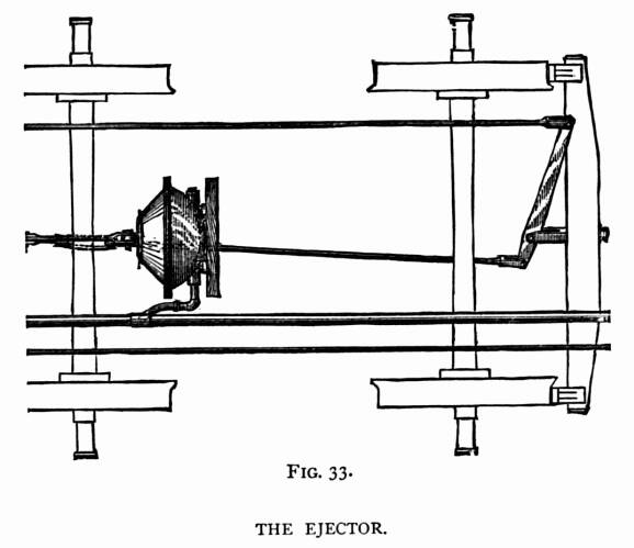 Under
each vehicle of a train, as seen in Fig. 33, a diaphragm is securely
fastened which performs the combined duties of cylinder and piston.
It consists of a kettle-shaped casting with a loose disk of heavy
rubbered duck fastened over its mouth; the center of the disk
being provided with an iron plate, through which passes an eye-bolt
for forming connection with the brake-lever. The inside of the
diaphragm is connected to the pipe which passes along the train,
and has its front end connected with the ejector on the locomotive. Under
each vehicle of a train, as seen in Fig. 33, a diaphragm is securely
fastened which performs the combined duties of cylinder and piston.
It consists of a kettle-shaped casting with a loose disk of heavy
rubbered duck fastened over its mouth; the center of the disk
being provided with an iron plate, through which passes an eye-bolt
for forming connection with the brake-lever. The inside of the
diaphragm is connected to the pipe which passes along the train,
and has its front end connected with the ejector on the locomotive.
THE EJECTOR.
The position of the ejector in the cut can be clearly
seen in Fig, 34, where there is also a diaphragm to be seen under
the deck where it is located when used to operate driver brakes.
The ejector is operated on the same principle as the water injector,
only it is used to lift air instead of water. A cross-section
of the injector is shown in Fig. 34. When the engineer wishes
to apply the brake, he pulls the handle 41 (broken off in the
cut), which opens the valve B49, and admits steam to the
body of the ejector A1. The steam rushes upward round the
end of the tube 5, its velocity being accelerated in passing through
the 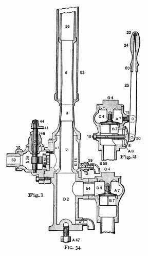 contracted
opening left round the top of the tube. Passing through tubes
3 and 6, the steam shoots up in the form of a column with a hollow
base; the tube 5, which is connected with the pipes and diaphragms
on the train, forming this base. The effect of the steam passing
out under these conditions is to induce a current through the
tube 5, which draws up the valve B7, and sucks the air
out of the pipes and diaphragms. A vacuum being thus formed in
the diaphragms, the atmosphere presses the flexible ends together.
This tendency to collapse is retarded by the brake-rod connections,
and the latter receive a pull equal to the combined atmospheric
pressure on the diaphragm. The brake-levers are arranged to transmit
a proper tension to the brake-shoes for making the brake effective.
A vacuum gauge placed on the front of the ejector enables the
engineer to regulate the power as he wants it. The brake is released
by pushing on the lever 24, which opens the valve 8, and admits
air into the brake-pipes. The release-valve attachment is sidewise
in vertical section cut through the handle, and is put separate
for convenience of illustration. contracted
opening left round the top of the tube. Passing through tubes
3 and 6, the steam shoots up in the form of a column with a hollow
base; the tube 5, which is connected with the pipes and diaphragms
on the train, forming this base. The effect of the steam passing
out under these conditions is to induce a current through the
tube 5, which draws up the valve B7, and sucks the air
out of the pipes and diaphragms. A vacuum being thus formed in
the diaphragms, the atmosphere presses the flexible ends together.
This tendency to collapse is retarded by the brake-rod connections,
and the latter receive a pull equal to the combined atmospheric
pressure on the diaphragm. The brake-levers are arranged to transmit
a proper tension to the brake-shoes for making the brake effective.
A vacuum gauge placed on the front of the ejector enables the
engineer to regulate the power as he wants it. The brake is released
by pushing on the lever 24, which opens the valve 8, and admits
air into the brake-pipes. The release-valve attachment is sidewise
in vertical section cut through the handle, and is put separate
for convenience of illustration.
CARE OF THE BRAKE.
The valve B7 of the ejector needs grinding occasionally;
and, if the lift should be too great, the valve will hammer the
seat out of shape. Sometimes when waste or other fibrous impurities
are sucked through the pipe, they stick in this valve, keeping
it away from the seat. The valve, is very easily reached by taking
off the cap O4. The steam-valve B49 needs about
the same care as any other steam-valve, and its troubles are of
the same nature. The shoulder at the top of the tube 5, which
is used to obstruct the steam, thereby increasing the velocity
of the quantity that passes, sometimes gets cut into channels
with the fast moving steam striking it. This reduces the promptness
of the ejector's action, but it is a form of deterioration that
proceeds very slowly. Care must be taken to keep the drip-valves
A and B16 in order, otherwise there may be trouble
with the ejector throwing water, or freezing up if the engine
stands where that apparatus will get cold in winter.
Table of Contents
| Contents Page
|